Installation
Transport System Installation
MagneMover LITE User Manual 249
Rockwell Automation Publication MMI-UM002F-EN-P - October 2022
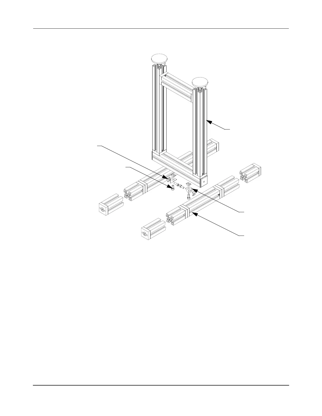
3. Attach the parallel path legs at the appropriate locations (if not already installed) as
shown in Figure 5-3.
Figure 5-3: Legs on a Parallel Path Beam Assembly
A. Insert one M8 T-nut and rotate into position in the channel on the side of each
beam at the position for the leg. T-nuts must be inserted so that the spring steel
tabs are facing toward the beam, then rotated clockwise into place.
B. Insert one M8 T-nut and rotate into position in the channel on the top of the leg
to attach the beam.
C. Position the leg over the T-nuts and use a machinist square to make sure that it
is properly positioned.
D. Locate an angle bracket at each beam/leg junction, apply Loctite 243 to two
M8 x 25 mm screws per bracket and install. Tighten enough to secure the
bracket while still allowing it to move.
NOTE: Make sure that the angle bracket is configured for 50 mm use by
placing the inserts into the bracket with the hole in the insert to the
outside of the bracket as shown in Figure 5-4.
Leg Stand Assembly
M8 T-Nut
(4X)
M8 x 25 mm Screw
(4X)
Beam
Angle Bracket
(2X)
 Loading...


