Installation
Transport System Installation
MagneMover LITE User Manual 251
Rockwell Automation Publication MMI-UM002F-EN-P - October 2022
Leveling the MagneMover LITE
Once the stand assembly is complete and the transport system is properly located, make sure
that all sections of the beam are level.
1. Establish a datum for the system (interface to existing equipment, and so on).
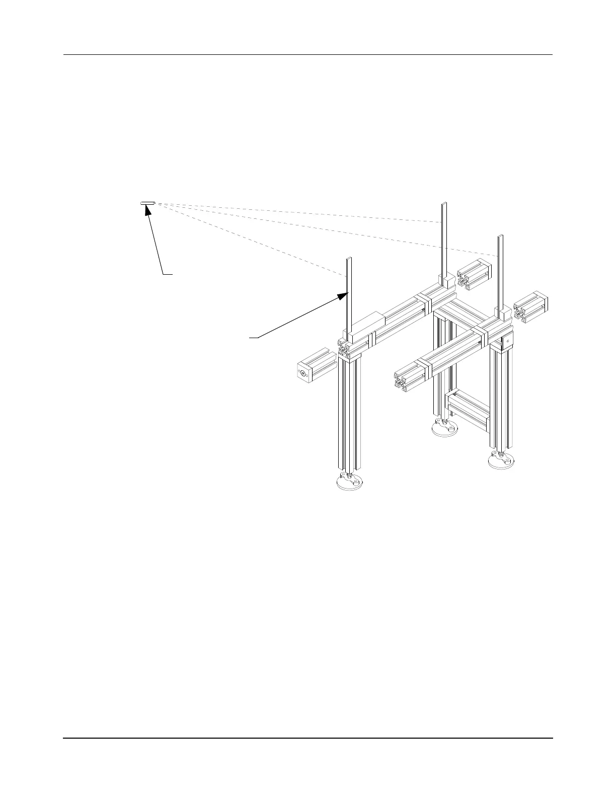
2. Use a laser level to identify the datum throughout the installation area as shown in
Figure 5-5.
Figure 5-5: System Leveling
3. Make sure that all sections of the beam are level and correctly referenced to the datum.
A. Place a machinist square vertically on the beam at each location where a foot is
located below the beam. Reference the location of the laser beam on the
machinist square for the following steps.
B. Adjust the feet on the legs as required to reach the required height with a
14 mm Hex wrench.
C. Lock the feet into position by tightening the jam nut against the leg with a
17 mm Hex wrench.
D. Repeat for each foot.
Laser Level
12” Machinist Square
 Loading...


