Reference Modification no.
- 4 -
Page
114
Date
2002 01 01
Main
914 F
01477
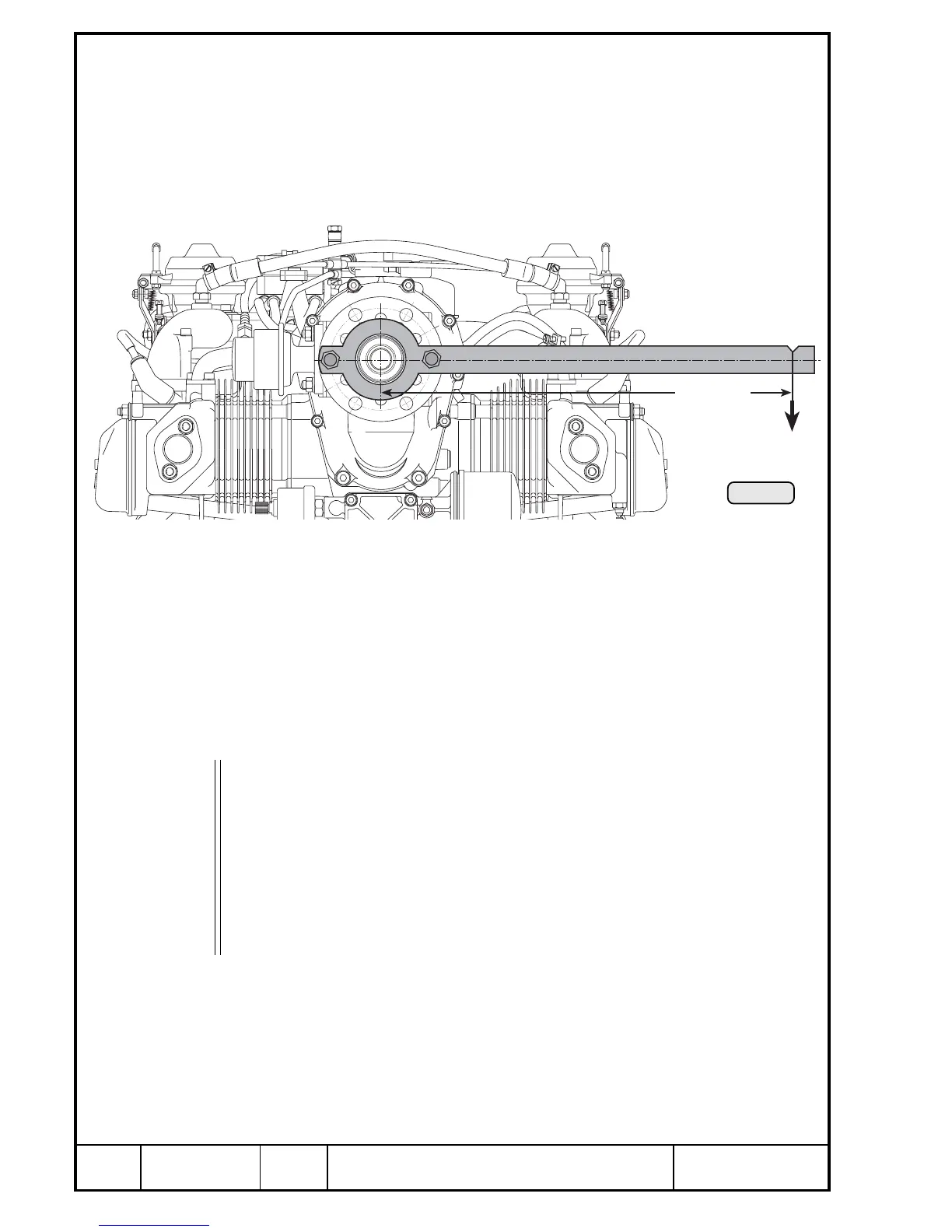
Pic. 59
12.4.2) Checking of the overload clutch
See Pic. 59.
To be carried out at overhaul or at suspicion of slipping. Inspection is done
with crankshaft locked. Remove plug screw from crankcase, p.t.o. side, and
insert crankshaft locking screw, part no. 240 880. Turn in until the screw
engages noticeably in the crankweb recess. (see chapter 13.3.1).
Fit a specially prepared lever to the propeller flange (e.g. length 1,5 m / 5 ft.)
and determine slipping torque with a spring scale. Applicable is the value
determined during slow turning motion. Repeat the measurement several
times to get a stable value.
▲ WARNING: Always observe the requisite safety instructions. Non-com-
pliance could result in personal injury.
The slip moment is calculated from the spring force (F) measured in N and
the length of the lever arm (L) applied in m (N x m = Nm).
Slipping of the clutch must occur between 600 and 800 Nm (440 and 590
ft.lb.).
■ CAUTION: Do not exceed 800 Nm (590 ft.lb.) otherwise internal dam-
age can occur.
If the torque is below or above this value, inspect, repair or overhaul the
propeller gearbox in accordance with the instructions for continued airworthi-
ness.
- Detailed inspection of all gearbox components.
Kraft F in N

 Loading...


