Reference
Modification no.
- 0 -
Page
24
Date
1997 02 01
Main
914 F
01476
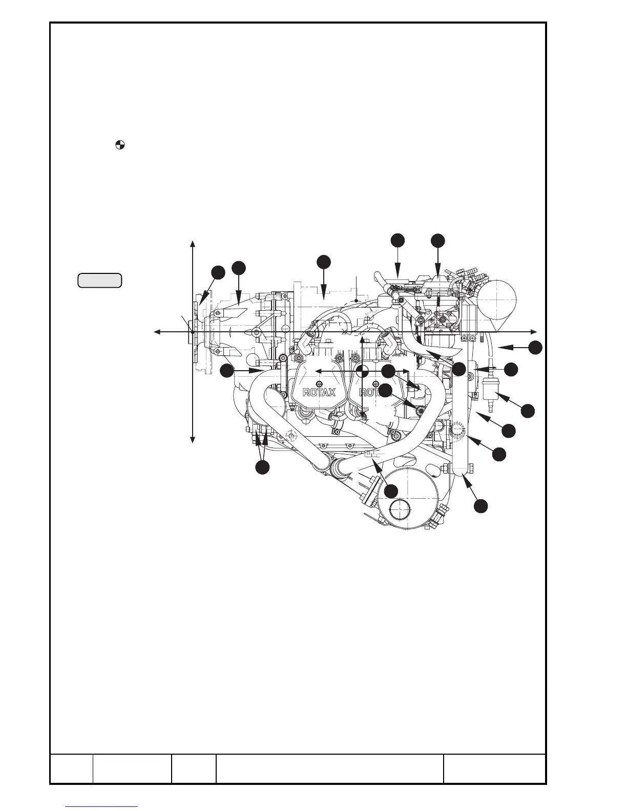
7.3) Engine components, engine views, numbering of cylinders, definition of main
axes
See illustration Pic. 5/6/7/8 and 9.
PTO power take off side
MS magneto side
A points of attachment for engine transport
centre of gravity
P zero reference point for all dimensions
◆ NOTE: Allow ±1 mm on all stated dimensions as manufacturing tolerance
x,y,z axes for system of coordinates
Cyl. 1 Cylinder 1
Cyl. 2 Cylinder 2
Cyl. 3 Cylinder 3
Cyl. 4 Cylinder 4
Q engine number
W propeller flange
E propeller gear
R vacuum pump or hydrau-
lic governor for constant
speed propeller
T intake manifold
Y ignition housing
U ignition cover
I constant depression carb
O airbox
P engine suspension frame
{ stainless steel exhaust
system
} turbocharger
q turbo control unit (TCU)
w fuel pressure control
e servo motor
r servo cable
t cable assembly
y coolant pump
u expansion tank
i 2 separate oil pumps
o connection for oil return
line (engine)
p connection for oil return
line (turbo)
[ oil filter
] electric starter
A electronic modules for
ignition
S compensation tube
D connection for manifold
pressure
F sensor for oil pressure
G sensor for oil temperature
H sensor for cylinder head
temperature
J 2x pressure sensor
K connection for mechanical
rev-counter
L connection for additional
temperature sensor
(airbox)
: drip tray
a water trap
s three way solenoid valve
d 2x electric fuel pump
f oil tank
g external alternator
h external alternator
Pic. 5
+z
-z
+x
-x
P
+z1
-x1
+x1
-z1
A
MS
PTO
2
8
7
24
21
3
4
18
10
20
32
35
34
00120
19
7
6
40

 Loading...


