Reference
Modification no.
- 3 -
Page
240
Date
1999 01 01
Main
914 F
01480
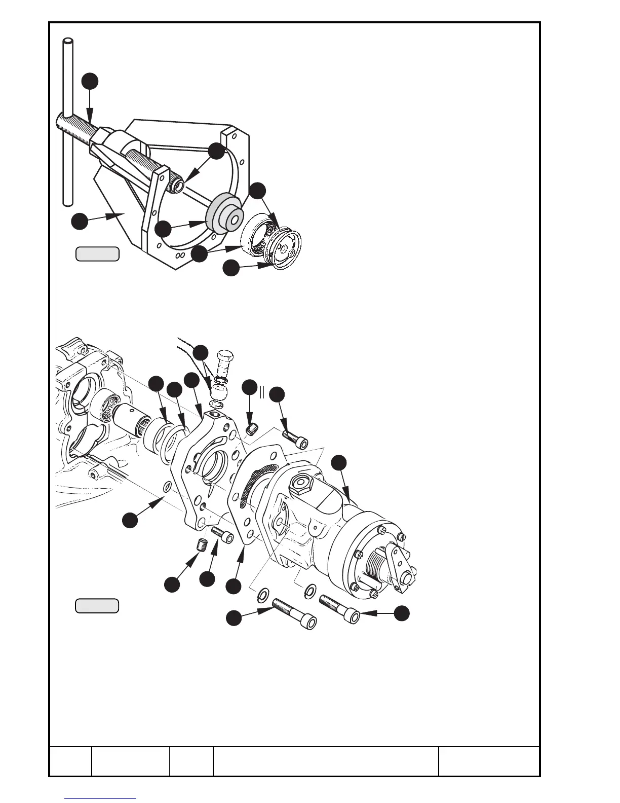
14.4.9) Drive of propeller governor - installation
See Pic. 225 and 226.
Installation of needle sleeve and ball bearing as described in chapter 14.4.6).
Grease new O-ring Q and insert it together with oil inlet flange W into
crankcase. Take care that both M6 threads are horizontal and the opening is
in a position to let the oil pass. For better positioning tighten governor flange
only slightly with 2 Allen screws M6x20 and oil inlet
flange with 2 Allen screws M6x16.
Screw extractor E, part no. 877 615 onto crankcase,
place adaptor R 877 590 into roller bearing T, place
it on centering Y and press it with spindle U fully
home into crankcase. Fit circlip in groove with its
sharp edge towards outside.
■ ATTENTION: The oil inlet flange must be
fitted well aligned and the O-ring must not be
squeezed.
Remove governor flange I again. Fit dis-
tance sleeve O and new O-ring P 32x4 into the crankcase. Place one each
O-ring { 7x2 into the oil inlet flange and into governor flange and keep them
in position with some grease. Place governor flange and fix it with 4 Allen
screws } M6x20 on crankcase and with 2 Allen screws q
M6x16 on oil inlet flange.
■ ATTENTION: Longer screws will damage the oil
inlet flange.
◆ NOTE: Tightening torque 10 Nm (90
in.lb). Secure both Allen screws for oil inlet
flange with LOCTITE 221.
Fit propeller governor w and new
gasket e with 3 Allen screws r
M8x40 and 1 x M8x35 with lock
washers and tighten to 22 Nm
(195 in.lb). Take care that
teeth engage.
◆ NOTE: The 35 mm
(1,38 in.) long screw
t to be mounted on
bottom left side.
Fit pressure oil hose
y on governor flange
and on oil pump hous-
ing and secure with
hose clamp. The plug screws u and i remain normally closed. On position
u a pressure gauge for governor pressure observation can be connected.
The maximum control pressure is between 22 and 25 bar (320 ÷ 360 p.s.i.).
The governor starts regulating at 3600 ÷ 3700 r.p.m.
3
Pic. 225
Pic. 226
12
13
15
18
20
8
10
9
19
14
11
17
16
6
7
5
4
1
2
00258
1
00259
12

 Loading...


