Reference Modification no.
- 3 -
Page
54
Date
1999 01 01
Main
914 F
01476
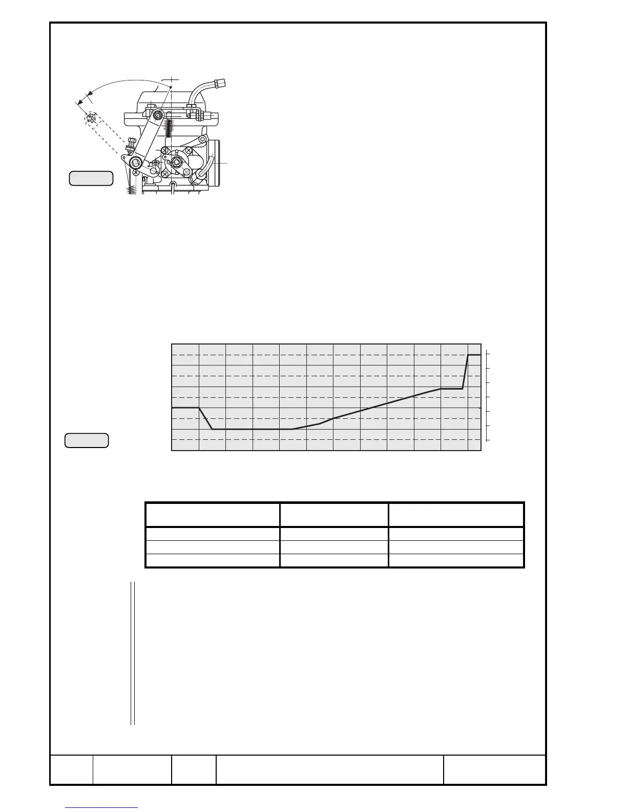
9.5.2) Turbo charge control
9.5.2.1) Control of boost pressure in the airbox
See Pic. 27/28 and 29.
The position of the carb throttle position is signalled by a
potentiometer to the TCU where it is transformed in a chosen
pattern into target pressure in the airbox.
◆ NOTE: The position of the carb throttle is devided
linear from 0 to 115 %.
After comparison of the actual airbox pressure with the target
pressure the position of the waste gate will be varied by a
servo motor until equalizing of the pressures.
◆ NOTE: With carb throttle closed, although with hardly
any exhaust energy at disposal a high boost pressure is
specified. The waste gate will then be completely closed
and the length of the Bowden cable can be verified or
adjusted.
For correlation between throttle position and the target pressure in the
airbox refer to the diagram (Pic. 28).
The most important points for engine operation:
■ ATTENTION:No steady engine operation is planned between max. con-
tinuous power (108 ÷ 110 %) and take-off performance (115
%). Therefore the target pressure rises rapidly between the
respective throttle positions and it should not be tried to
remain in this phase but to move speedily through this range
in both directions to prevent control fluctuations.
◆ NOTE: In the course of model refinement some parameters have
been slight changed. Diagram and table show the presently
valid state of software.
100%
115%
0%
Pic. 27
Pic. 28
00137
00474
28
1400
1300
1200
1100
1000
900
0 10 20 30 40 50 60 7 0 80 90 100 110 115 %
30
32
34
36
38
40 in. HG
00647
engine performance throttle position nominal airbox pressure
idling of engine ~ 0 % 1100 hPa (32,5 in. HG)
max. continuous performance 100 ÷ 108 % 1190 hPa (35,1 in. HG)
take-off performance 110 ÷ 115 % 1350 hPa (39,9 in.HG)

 Loading...


