Reference Modification no.
- 0 -
Page
164
Date
1997 02 01
Main
914 F
01478
13.4) Ignition system
Besides the maintenance work prescribed in Chapter 12) and description of the
ignition system in Chapter 9.4), further maintenance work is described below.
In principle the ignition unit requires no maintenance. Before, however, dismantling
the ignition unit it is useful to trace defects by trial and error method.
13.4.1) Checking of ignition unit, trouble shooting
Components can only be exchanged but not repaired. If there is no spark,
systematically trace for possible cause.
▲ WARNING: For safety’s sake, switch off ignition, if possible, and with-
draw ignition key!
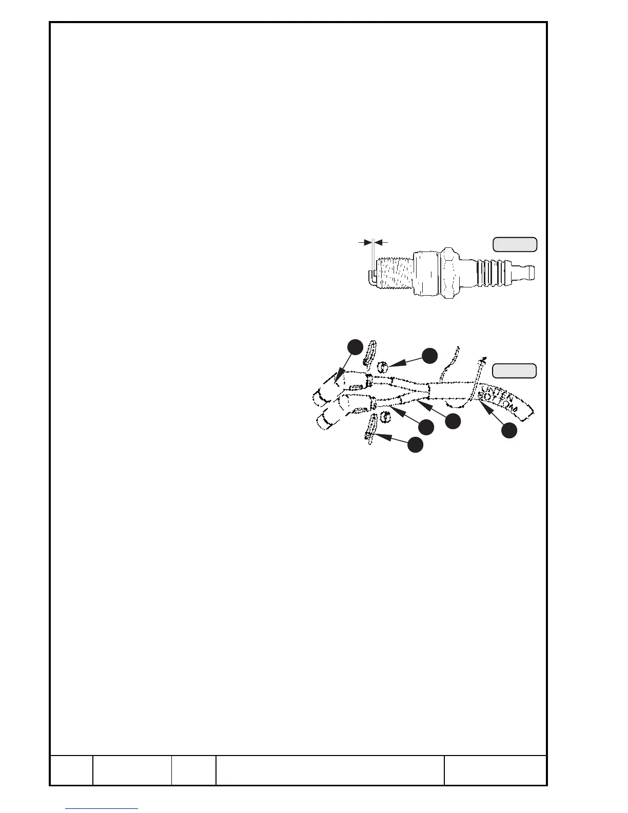
13.4.2) Spark plugs, ignition cables, spark plug connectors, cables
See Pic. 129 and 130.
— Check of the resistance spark
plugs. Check electrode gap , see
dimension Y) and caloric value.
See Chapter 8).
— Visually check resistance spark plug connector Q. Assure security of the
spark plug connector. Minimum withdrawal force is 30 N. The spark plug
connector is screw-fastened to
the ignition cable W and se-
cured with a cable clamp
E. At visible wear renew
spark plug connector.
— Check for correct connec-
tion of the ignition cables
W, as per Wiring Diagram
(see Pic. 138).
The cable ends are furnished with coding sleeves R. The ignition cables
for the bottom spark plugs are protected by glass fibre/silicone protection
hose T. All ignition cables are covered by a protection hose Y — renew
at visible wear.
Resistance spark plug connector ............. .....................4,4 ÷ 6,0 kΩ
— Check all cables and their plug connections for damage and correct
connection as per Wiring Diagram (see Pic. 138).
— Check all plug- and screwed connections for oxidation and tight fit.
— Check short-circuit cables and ignition switch. If an ignition switch failure
is suspected, the short-circuit cable can be withdrawn from the ignition
switch.
Pic. 130
1
4
5
2
3
6
Pic. 129
00086
Y
00397

 Loading...


