ReferenceModification no.
- 5 -
Page
267
Date
2003 03 01
Main
914 F
d03052
Pic. 284
05618
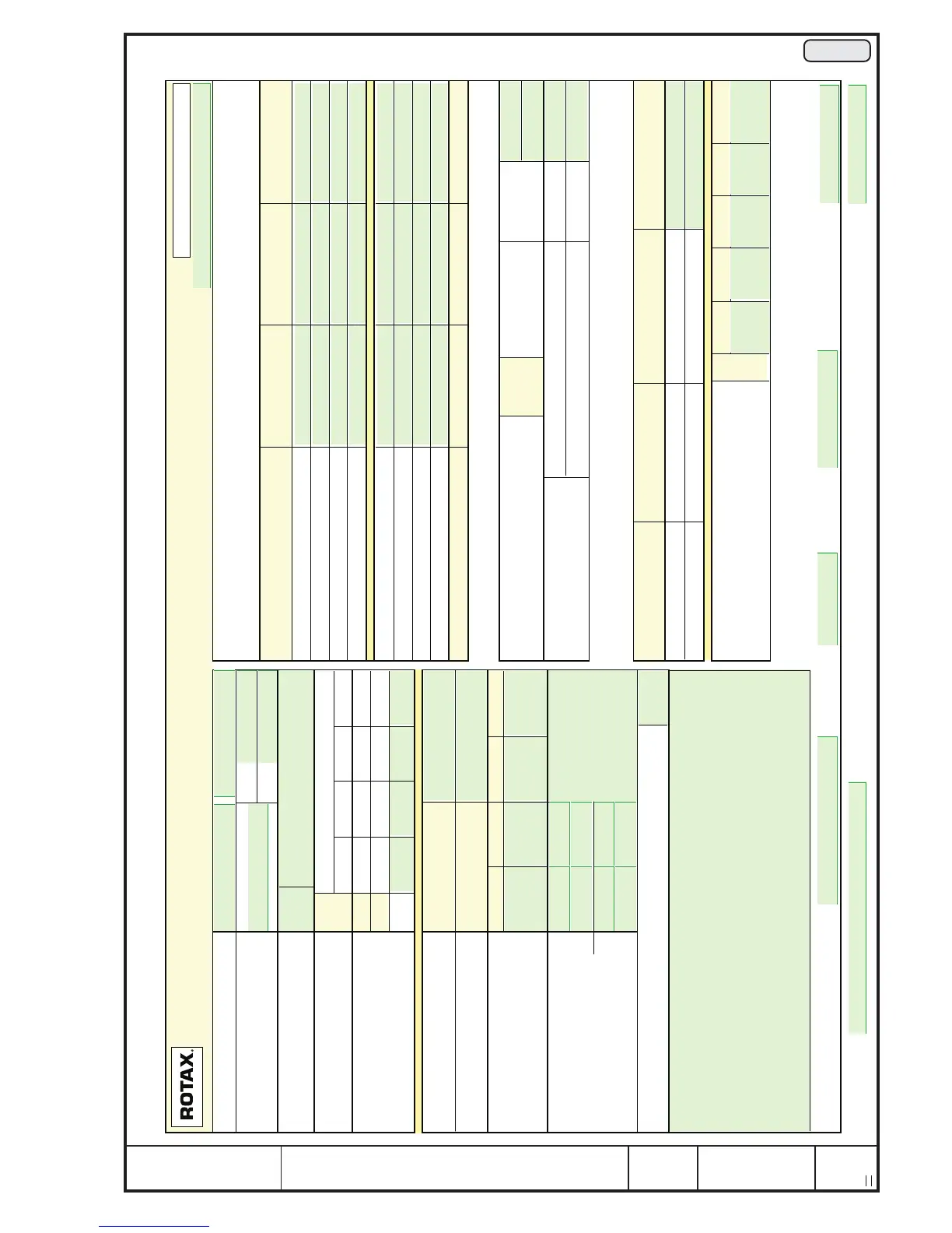
16.2) Form Sheet for igniton unit
AIRCRAFT ENGINES
Prüfprotokoll für Zündanlage / Inspection protocol for ignition unit
(mit "Klammergeber" / with "clamps pick up")
Type, S/N / engine type, S/N:
Zündanlage, S/N.:
Ignition unit, S/N:
TSN
TSO
Sichtkontrolle:
Visual check:
Geber-Zuordnung: Zündkreis / Ignition circuit
Pick-up coordination: A 1/2 A 3/4 B 1/2 B 3/4
Zündspule: Einschaltdrehzahl 912 1T / 2T 3B / 4B 1B / 2B 3T / 4T
max. 220 1/min 914 1T / 2T 3T / 4T 1B / 2B 3B / 4B
Ignition coil:
start r.p.m. max. 220 r.p.m.
Abstellkontrolle: Kreis A Zündfunke "AUS"
Ignition stop check: Circuit A Spark "OFF"
Abstellkontrolle: Kreis B Zündfunke "AUS"
Ignition stop check: Circuit B Spark "OFF"
Zündverstellung bei: A 1/2 A 3/4 B 1/2 B 3/4
(max. 1000 1/min)
Ignition variation at:
(max. 1000 rpm)
SMD-Modul oben.S/N,TNr:
SMD-modul, top S/N, p/n:
SMD-Modul unten S/N,TNr:
SMD-Modul bottom
S/N, p/n:
Zündspannung kV / Ignition Voltage / kV
Zündkabel
Ignition cable
n = 250 n = 500 n = 5000
1 TOP
2 TOP
3 TOP
4 TOP
1 BOTTOM
2 BOTTOM
3 BOTTOM
4 BOTTOM
Mindestwerte / min. values (kV) 14 20 20
Stator mit Ohmmeter geprüft / Stator tested with Ohmmeter:
Ladespulen (2 Stück) Kreis A gegen Masse soll / nom.
Charging coils (2 pieces) circuit B against ground 3,2 ÷ 4,5 W
Lichtspulen (8 Stk.)
Lighting coils (8 pieces)
in Serie (gelb-gelb) / in series (yel-yel) 0,1 ÷ 0,8 W
gegen Masse / against ground ´
Prüflauf mit Fremdregler und 12V 36 Ah Batterie (geladen)
test run with external regulator and 12V 36 Ah (loaded)
Drehzahl / speed Lampenbelastung Spannungsanzeige soll Spannungsanzeige ist
R.P.M. load / bulbs voltage nomin. voltage actual
4000 1/min 14,0 ± 0,3 V
4000 1/min 150W 13,2 ± 0,5 V
Geberwiderstand (weiß/gelb blau/gelb)
A 1/2 A 3/4 B 1/2 B 3/4
Drehz./rev.
Pick-up resistance (white/yel. blue/yel.)
(bei offener Steckverbindung/with open connector)
Unterschrift Prüfer / Signature Tester: Datum / Date: Abt. / Dept.: Auftr. Nr. / order no.:
HV-Test:
Geprüft mit 5 kW Stecker und 50 pF Kondensator, offen, kein Funkenüberschlag /
Tested with 5 k W spark plug connector and 50 pF capacitor, open, no flash over.
Vert. / Co.: AA,
Kunde / Client :
Type
Anschlußbelegung gem. Schaltplan GÜ-Handbuch Bild Nr.156 kontrolliert
wire connection checked according circuit diagram, overhaul manual fig.156
Formblatt Nr. 17-045/G02 10 19
Druckdatum / date of print:
Bemerkungen / Remarks:
Bem. / rem.
Bem. / rem.

 Loading...


