Reference
Modification no.
- 0 -
Page
235
Date
1997 02 01
Main
914 F
01480
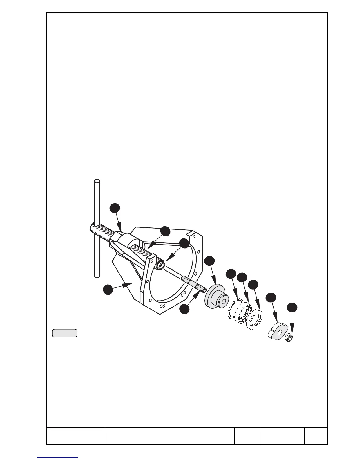
14.4.1) Removal of roller bearing for F2 only
See Pic. 215.
After the propeller gearbox is removed, the crankcase side propeller shaft
bearing and oil seal can be renewed if necessary.
Remove circlip Q with circlip pliers. Fit extractor assy W, part no. 877 615,
with 8 Allen screws M6x25 to the crankcase. Screw stud E M10x45/20, part
no. 941 180, into the pull-in spindle R, part no. 877 580, and fit hex. nut T
M24x,15 onto the spindle.
For better guidance push the adaptor Y, part no. 877 592, into the roller
bearing U and insert spindle into the extractor ass'y.
Place the puller plate I, part no. 877 560, onto the stud at the backside of the
crankcase and fix with hex. nut M10 O, part no.242 091.
Keep pull-in spindle with handle in position and turn hex. nut clockwise until
the roller bearing U with oil seal P is pulled out of the crankcase. Unscrew
hex. nut, remove adaptor plate with roller bearing and oil seal and withdraw
spindle. Remove extractor ass'y from crankcase.
■ ATTENTION: During this procedure the oil seal P is destroyed and must
be renewed.
5
4
12
6
1
7
10
8
9
2
3
Pic. 215
00248

 Loading...


