Reference
Modification no.
- 0 -
Page
51
Date
1997 02 01
Main
914 F
01476
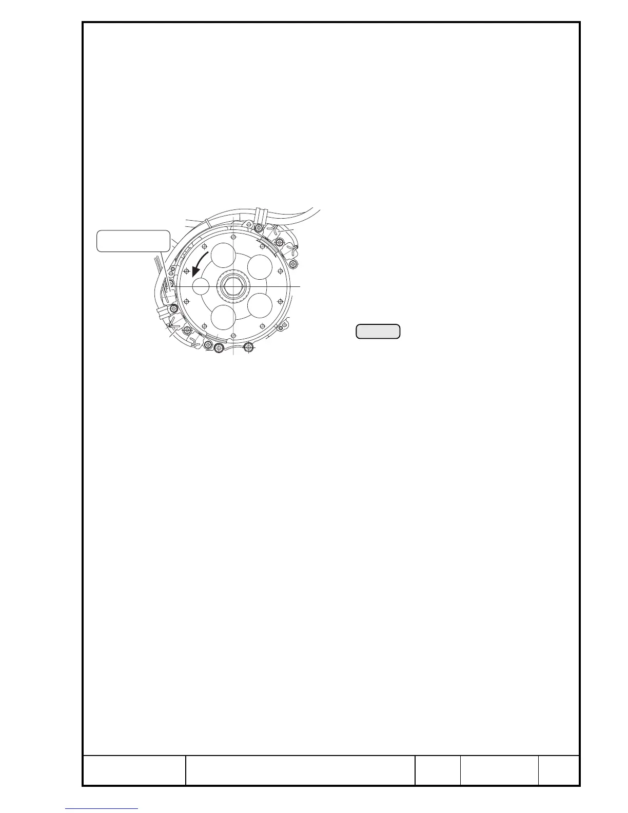
9.4.2) Allocation of trigger coils and ignition circuits
See Pic. 25.
The top placed trigger coils A1/2 and A3/4 (in approx. 5 mm higher position)
control in conjunction with the top electronic module the top spark plug of the
cylinders.
i.e.Ignition circuit A: top trigger coils ➍ top electronic module ➍
top spark plugs
Ignition circuit B: lower trigger coils ➍ lower electronic module ➍
lower spark plugs
Legend to Pic. 24 and 25:
Designation of trigger coils.
e.g. A3/4 ➍ controls ignition of the top spark plug
of cyl. 3 and 4 (ignition circuit A)
B3/4
A1/2
A3/4
B1/2
Drehzahlmesser
rev. counter
Pic. 25
9.4.3) Firing order
The firing order is 1 - 4 - 2 - 3.
9.4.4) Ignition cables
The 8 ignition cables are marked with number 1 through 4 for cylinder
assignment. 2 cables each are routed together in a protective hose between
the cylinder heads.
◆ NOTE: These ignition cables can only be routed into position
without spark plug connector.
The connection of ignition cable on ignition coil and spark plug connector is
by threaded prong, thus enabling easy exchange.
00135

 Loading...


