Reference Modification no.
- 0 -
Page
168
Date
1997 02 01
Main
914 F
01478
A1/2
A3/4
B3/4
B1/2
5
A1/2
A3/4
B3/4
B1/2
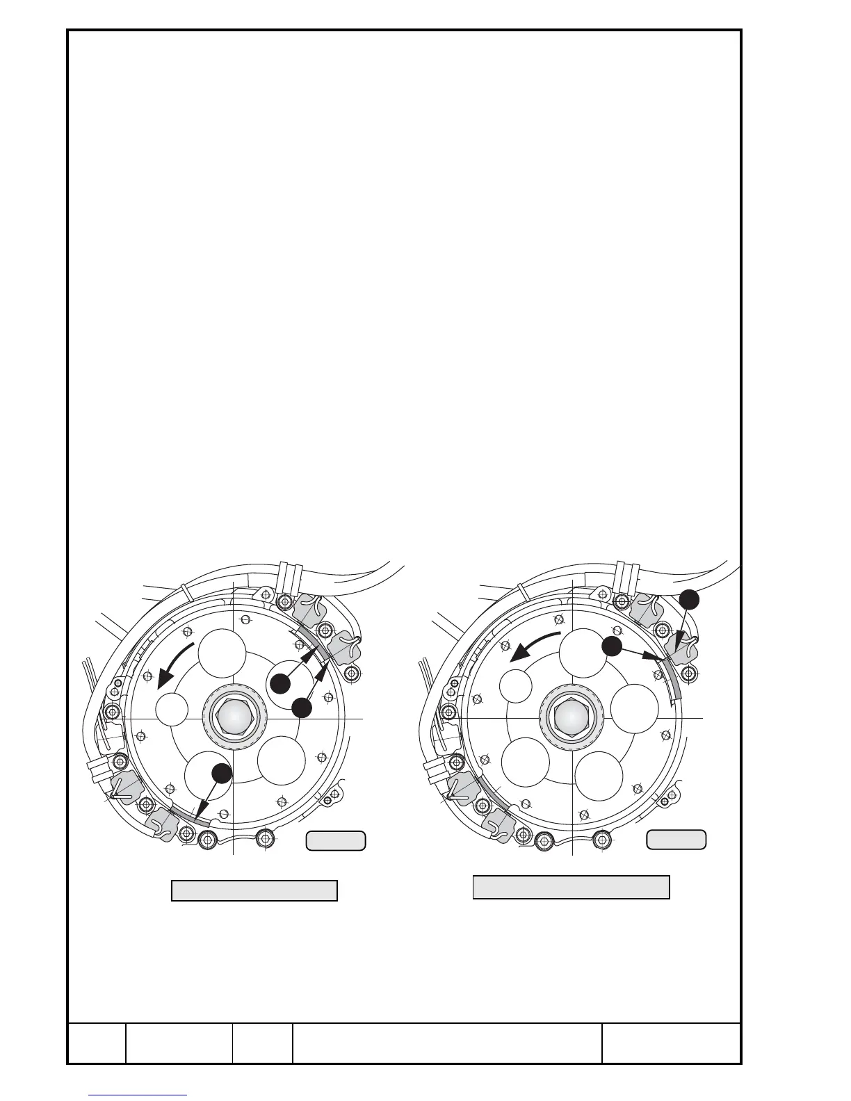
13.4.8) Ignition timing control
See Pic. 136 and 137.
The automatic ignition timing control is actuated by the trigger cam Q on the
flywheel hub of ignition circuit A or trigger cam W of ignition circuit B.
Transition from start ignition timing to operating ignition timing takes place
between 650 and 1000 rpm.
Check with stroboscope and inductive pliers (see Chapter 13.4.8).
For this procedure, connect stroboscope to battery and clamp inductive pliers
to the ignition cable of cylinder "1 top". This spark plug is actuated by the
trigger coil A1/2.
At an engine speed of 150 to approx. 650 r.p.m. the trailing edge E of the
trigger cam aligns with the core R of the trigger coil.
Trigger coil A1/2 serves the top spark plug of cylinder 1 and 2
Trigger coil A3/4 serves the bottom spark plug of cylinder 3 and 4
Trigger coil B1/2 serves the bottom spark plug of cylinder 1 and 2
Trigger coil B3/4 serves the top spark plug of cylinder 3 and 4.
After transition from start ignition timing to operating ignition timing the
leading edge T of the trigger cam aligns with the core R of the trigger coil.
This procedure can be performed on all 4 trigger coils, taking into considera-
tion the corresponding ignition cable, see Pic. 138.
3
4
2
1
Pic. 137
Pic. 136
00087
00088
Start ignition timing
Operating ignition timing

 Loading...


