Reference
Modification no.
- 0 -
Page
255
Date
1997 02 01
Main
914 F
01480
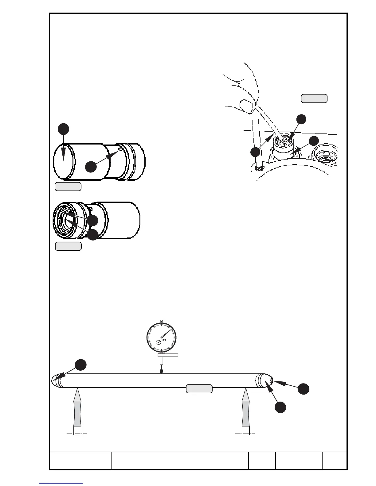
14.7) Hydraulic valve tappets
See Pic. 264, 265 and 266.
Remove valve tappet Q from crankcase using a specially shaped screwdriver W.
Never engage at circlip E. This could cause valve tappet to fall apart.
■ ATTENTION: Lay aside tappets in a
manner to ensure refitting
in their initial place.
Check valve tappet visually. The tappet
rotates during operation. Therefore the cam
contact surface R is worn evenly. If the
tappet does not rotate, the contact face will
be worn unevenly. In case of uneven wear
replace the tappet. The tappets are not allowed
to be ground on their face!
If a valve tappet must be re-
placed, check carefully the
respective cam on camshaft.
Taking apart valve tappets is
not planned and not neces-
sary.
The new valve tappet is supplied dry and will fill itself full with oil
during starting procedure. Oil enters the valve tappet through bore
T. The securing ring E keeps the valve tappet plunger Y in
position when the tappet is removed.
■ ATTENTION: The first cranking of a repaired engine should be
without ignition, until the required oil pressure is built up.
14.8) Push rods
See Pic. 267.
Clean push rods Q and inspect them visually. Pay attention to tight fit of the two ball
heads W pressed into the rod. Excessive engine speed may have caused bending
of the push rods. Check push rods for straightness. Through the bores E oil passes
from the valve tappet to the rocker arm.
5
Pic. 266
Pic. 265
4
2
Pic. 264
6
3
3
1
0
10
20
30
40
50
60
70
80
90
0.01mm
1
2
3
4
5
6
7
8
9
0
2
Pic. 267
Q
3
2
00301
00300
00302
00299

 Loading...


