Reference Modification no.
- 0 -
Page
146
Date
1997 02 01
Main
914 F
01478
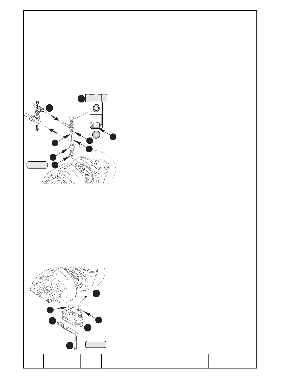
13.2.2) Check valve (Turbo)
See Pic. 98.
Remove banjo screw Q M8 with sealing rings W 8x13.
◆ NOTE: The valve housing E is only removed in case of damage or
for cleaning.
Remove ball R 5,5 and spring T, 22 mm long, from valve housing.
◆ NOTE: The banjo screw together with ball and spring serves as
pressure check valve. For further information, see Chapter
9.3.2.
Check all components and check them visually.
Also check thread and flange surface of turbo charger
housing.
In case of leakage at valve seat Y it can be reworked with
valve lapping paste or other suitable method. If neces-
sary, renew banjo screw.
Reassembly in reversed sequence.
Insert valve housing E with sealing ring U 12x18 into
turbo charger housing and tighten to 25 Nm (220 in.lb).
Insert spring T and ball R.
Tighten pressure oil tube I with banjo screw Q and
sealing rings W on both sides. Tightening torque 10 Nm
(90 in.lb).
13.2.3) Oil sump container (Turbo)
See Pic. 99.
◆ NOTE: The oil sump container Q is only removed in case of
damage or for cleaning.
Remove spring from waste gate flap with a suitable tool.
Unscrew union nut W of turbo suction oil tube E. Remove the 2 Allen screws
R M6x55 and cable support T, from oil sump container Q and O-ring Y
9x2,3.
Clean all components and check them visually. Also check thread and flange
surface of tubo charger housing. In case of damage renew oil
sump container.
Reassembly in reversed sequence.
Fit oil sump container Q with O-ring Y, cable support T and
2 Allen screws U M6x55. Tightening torque 10 Nm (90 in.lb).
Tighten union nut W of turbo suction oil tube to 20 Nm (180
in.lb).
00075
Pic. 98
00075
Pic. 99
2
1
5
8
7
3
4
6
2
1
4
6
5
3

 Loading...


