ReferenceModification no.
- 0 -
Page
247
Date
1997 02 01
Main
914 F
01480
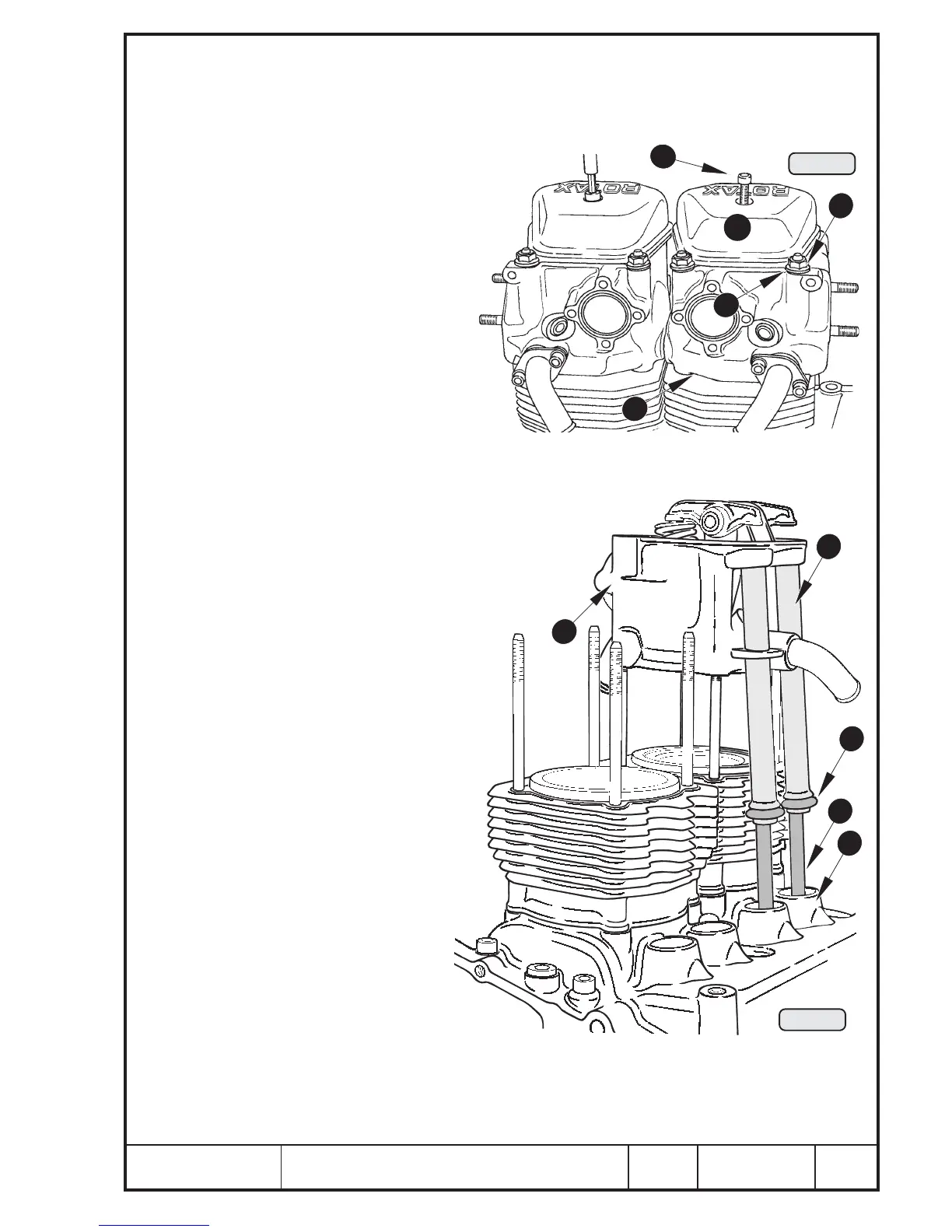
14.5) Cylinder head — removal
See Pic. 243 and 244.
If components of several cylinders are dis-assembled, they must be marked to ensure
correct coordination at re-fitting.
Remove Allen screw M6x25 Q and washer
from valve cover W and lift off valve
cover and large and small O-ring.
Remove crosswise 2 each collar
nuts E with washers R and 2 cap
nuts M8. The cap nut is inside
the valve cover and has a seal-
ing edge.
◆ NOTE: There is no washer
required under the
cap nut.
Lever complete cylinder head off with
screwdriver, levering between cylin-
der
TT
TT
T and cylinder head.
■ ATTENTION: Do not damage the sealing
surface!
Keep both push rods Y in oil return tubes
U in position, seal oil bore with finger
and remove cylinder head I. The oil
return tubes remain with the cylinder
head. Remove O-rings O 16x15 from
the oil return tubes or from crank-
case P.
Lay aside cylinder head so as
not to damage sealing surface
and oil return tubes. Lift out oil
filled push rods, stop oil from
dripping by sealing with fin-
ger. Coordinate push rods
with cylinder heads to pre-
vent any mix-up.
2
1
3
Pic. 243
7
9
6
8
4
5
10
Pic. 244
00278
00277

 Loading...


