Reference
Modification no.
- 0 -
Page
238
Date
1997 02 01
Main
914 F
01480
14.4.6) Drive for vacuum pump and propeller governor - re-fitting
See Pic. 219, 220 and 221
Lubricate new needle sleeve E. Position puller cap P, part no. 876 489 on
gearbox side, place press-in tool, part no. 877 579 { onto the needle sleeve
and fix with hex. nut }. Turning the hex. screw q clockwise, the needle
sleeve is pressed in completely.
The ball bearing W is pressed in with same procedure,
however, the puller cap P part no. 876 489 is fitted on
pump flange side, and the press-in tool w, part no.
877 595, is used.
Then press in new oil seal O with assembly punch,
part no. 877 276 and grease it. Apply LOCTITE 221
to countersunk screw U M5x12 and washer I for
ball bearing fixation and tighten.
Fit vacuum pump gear R and fix drive sleeve T
with holder, part no. 242 660. Apply LOCTITE 221
on Allen screw Y M8x14 and turn in.
■ ATTENTION: The length of Allen screw Y M8x14 must be absolutely
respected as otherwise the screw will collide with the drive
shaft of vacuum pump.
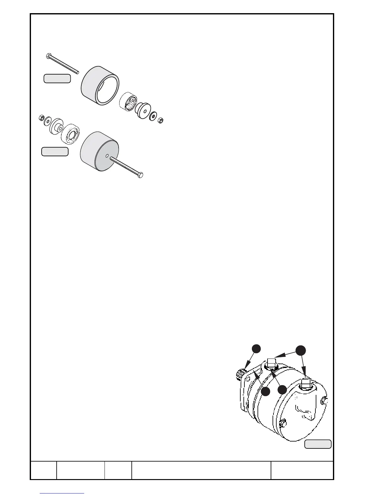
14.4.7) Vacuum pump
See Pic. 222.
The vacuum pump serves as drive of pneumatic inertial navigation instru-
ments.
◆ NOTE: The vacuum pump must not be taken apart and must be
renewed as complete unit, if necessary. Renewal during
overhaul at the latest.
Check teeth Q. Remove connections or plugs W from used vacuum pump. If
still in good condition they can be re-used. Renew damaged connections. For
fitting of hose connections, the pump can be clamped in a vice with drive
downward, using protective jaws.
■ ATTENTION: Only clamp on flange E. Never clamp the pump directly on
pump housing as this would damage the pump rotor. Never
install a pump that has been
dropped!
Spray connection threads R 3/8" NPT with
silicon and let dry. Do not use Teflon tape,
hose sealing lacquer or thread grease on the
connections. Only tighten connections with
ring- or socket wrench and bring them to
correct position. Retighten by max. 1,5 turn.
E
{
}
P
Pic. 220
q
P
}
w
W
Pic. 221
4
3
q
2
1
Pic. 222
00253
00254
00255

 Loading...


