Reference
Modification no.
- 0 -
Page
256
Date
1997 02 01
Main
914 F
01480
14.9) Fitting of piston and cylinder assembly
14.9.1) Fitting of hydraulic valve tappets
Lubricate bearing bore for valve tappets in crankcase. Apply LOCTITE Anti-
Seize to the contact surfaces of the valve tappets, lubricate their outside and
insert them according to the recorded position
into the crankcase. The valve tappet must
be able to turn in the crankcase with-
out resistance.
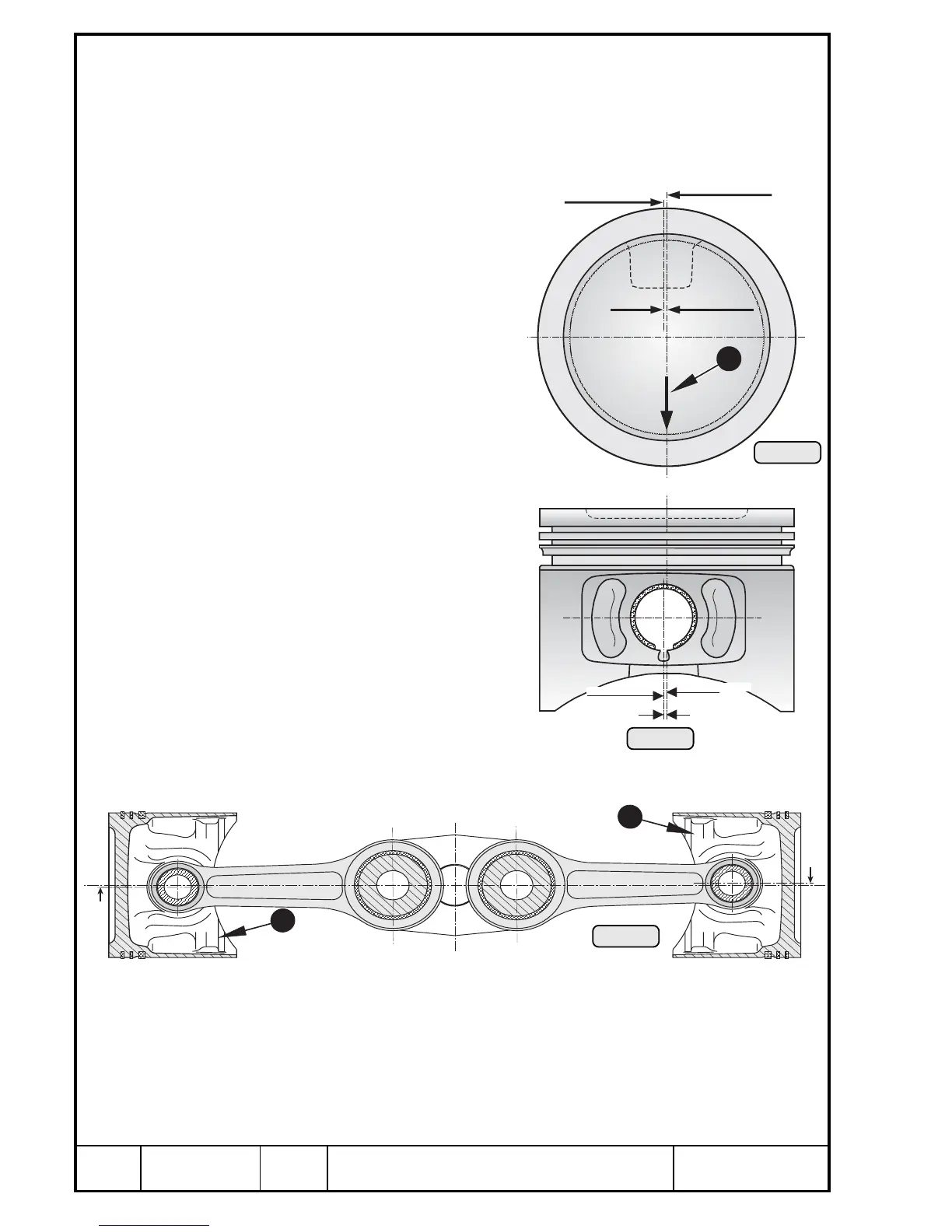
14.9.2) Fitting of pistons
See Pic. 268, 269, 270, 271, 272
and 273.
The piston pin centre is offset from
piston centre. At installation of the
pistons the arrow Q on the piston
crown has to point toward prop
shaft. Therefore on the pistons for
cylinder no. 1 and 3 the offsetting
(narrower side W) of piston faces
downwards, on cylinders 2 and 4
the offsetting (narrower side E)
faces upwards.
Install the piston as shown on Pic.
beside. The offsetting of piston pin
bore is 1 mm (.039 in.).
If the arrow Q on piston crown is
no more visible, the piston must be
measured.
1 mm
Kolbenachse
Bolzenachse
piston axis
pin axis
0,0394 in
1
piston centre
Nullhakenring /
circlip
Kolbenmitte /
1mm / 0,394 in
Bolzenmitte
pin centre

 Loading...


