Reference
Modification no.
- 0 -
Page
257
Date
1997 02 01
Main
914 F
01480
8
9
6
7
5
10
Pic. 271
4
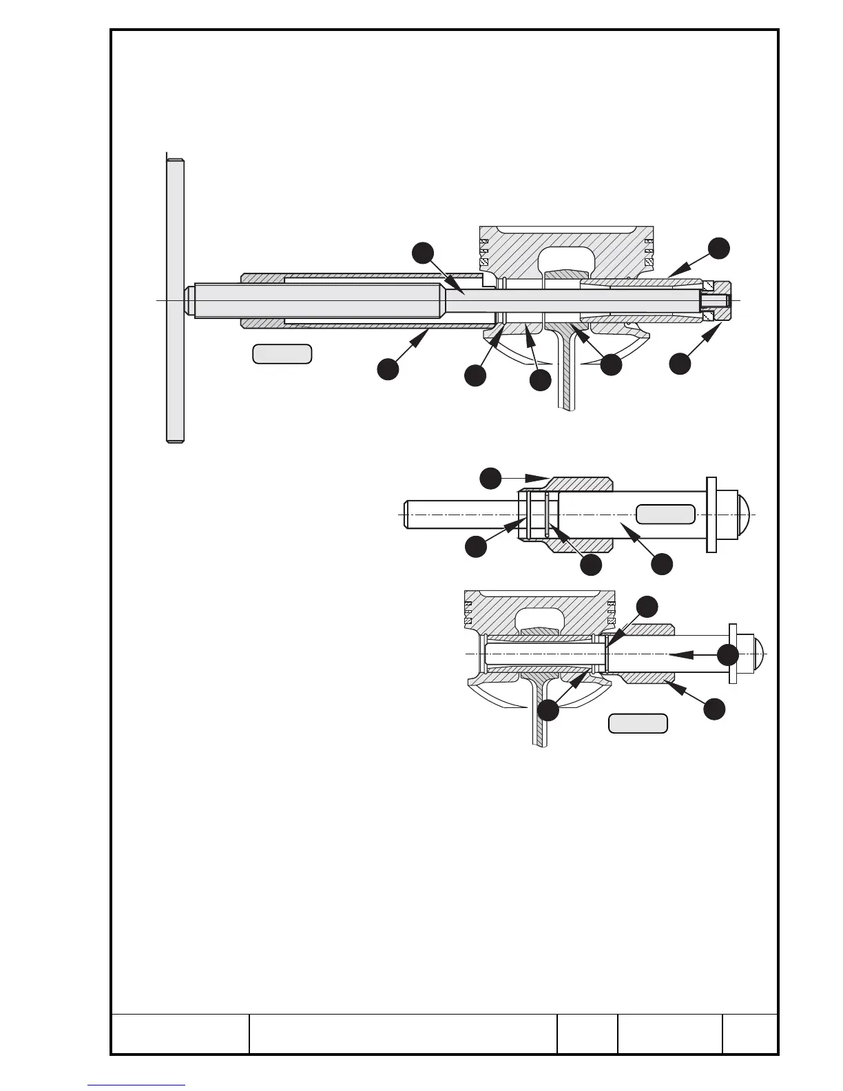
Apply MOLYKOTE G-N slide paste on the piston pin R. Also coat bore T in
conrod and bore Y in piston with MOLYKOTE G-N. Insert piston pin with
guide punch 877 011 (slide fit).
If this is not possible, the piston pin can be pulled in with the installation tool
U 877 016. Insert piston pin into one side of the piston bore, insert spindle of
installation tool I and fit nut O on end. Turning the spindle clockwise, the
piston pin can be drawn in completely till to the groove P.
Fit piston pin circlips with circlip installation tool 877 016. For this procedure
push the circlip {
with the insertion jig
} into the locating
sleeve q until it en-
gages in the groove
w.
Now position the
complete circlip installation
tool e on the piston. Sup-
port piston with hand and
push circlip { with a strike to
the insertion jig } into the
groove r of the piston. Apply
same procedure on the opposite
side of the piston.
■ ATTENTION: The opening of circlip must show downward, to 6
h
position,
to maintain tangential force of the circlip.
▲ WARNING: Always use new piston pin circlips!
Pic. 272
11
13
14
12
12
11
16
15
Pic. 273
00307
00308
00306

 Loading...


