Reference Modification no.
- 5 -
Page
140
Date
2003 03 01
Main
914 F
d03050
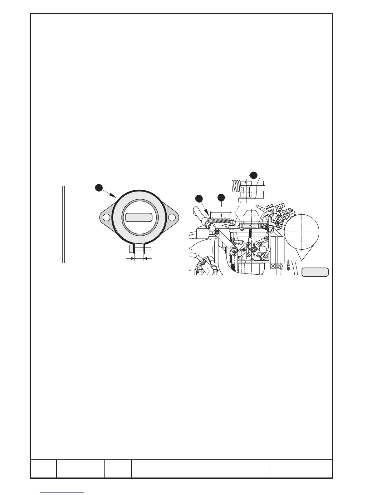
13.1.12) Reassembly of carburetors, carburetor flanges, fuel tubes and drip
trays
See Pic. 88/89 and 90.
The drip tray Q is fitted together with the carburetor flange W.
Fit carburetor flange, drip tray and new gasket E with 2 hex. screws R M8x25
and washers.
Secure screws with LOCTITE 221. Tightening torque 15 Nm (135 in.lb).
◆ NOTE: If leakage is noticed in the area of the drip tray, seal with
SILASTIC.
Insert aluminum spacer T 36/43/2,5 into carburetor flange. Fit carburetor in
carburetor flange free of grease and oil, align and fix with tube clamp Y.
From 1999 on the spacer ring is cancelled (see SI-912-004/SI-914-006, latest
issue).
■ CAUTION: Tighten the new carburetor flange only up to the prescribed
gap of 7 mm (.275 in.). See Pic. 88.
From field experience cases are known where the hose clamp was tightened
excessively. This may cause the flange to be scoured at the inside by the
carburetor rim possibly damaging it.
Check distance of 5 ÷ 6 mm (.20 ÷ .24 in.) on Allen screw U as this is important
to allow free movement of the spring I.
Engage spring with suitable tool on the bracket O.
■ CAUTION: To ensure efficient carburetor suspension, a distance of 40
mm (1.57 in.) between Allen screw and bracket must be
respected.
◆ NOTE: Now fit the 2 fuel tubes as this will no more be possible with
airbox mounted.
Fit fuel tube P with union nut { on carburetor (fuel inlet). Support the tube
with hose clamp } on carburetor bracket. Attach hose clamp with Allen
screws q M5x12 and nuts w. The tighten union nut to 10 Nm (90 in.lb).
Now the airbox e can be fitted on the connections of the carburetors. Do not
damage the previously fitted fuel tubes and pressure connection tubes.
Pay attention that all faces of attachment are free of grease.
00069
Pic. 89
7
9
8
5÷6 mm
40 mm
05529
7 mm (.275 in.)
Pic. 88
6

 Loading...


