ReferenceModification no.
- 2 -
Page
195
Date
1998 11 01
Main
914 F
01479
13.5.4.3) Assembly and adjustment
Position ascertaining of the servo motor:
See fig. 154 and 154/1.
For position ascertaining of the servo motor power-up the TCU.
◆ NOTE: After the automatic check of the servo motor } put the
throttle lever into idle position to make sure that the servo
motor will remain always in positon with waste gate
"closed". The servo motor is self locking.
Position ascertaining is absolutely necessary for correct
adjusting of the servo cable.
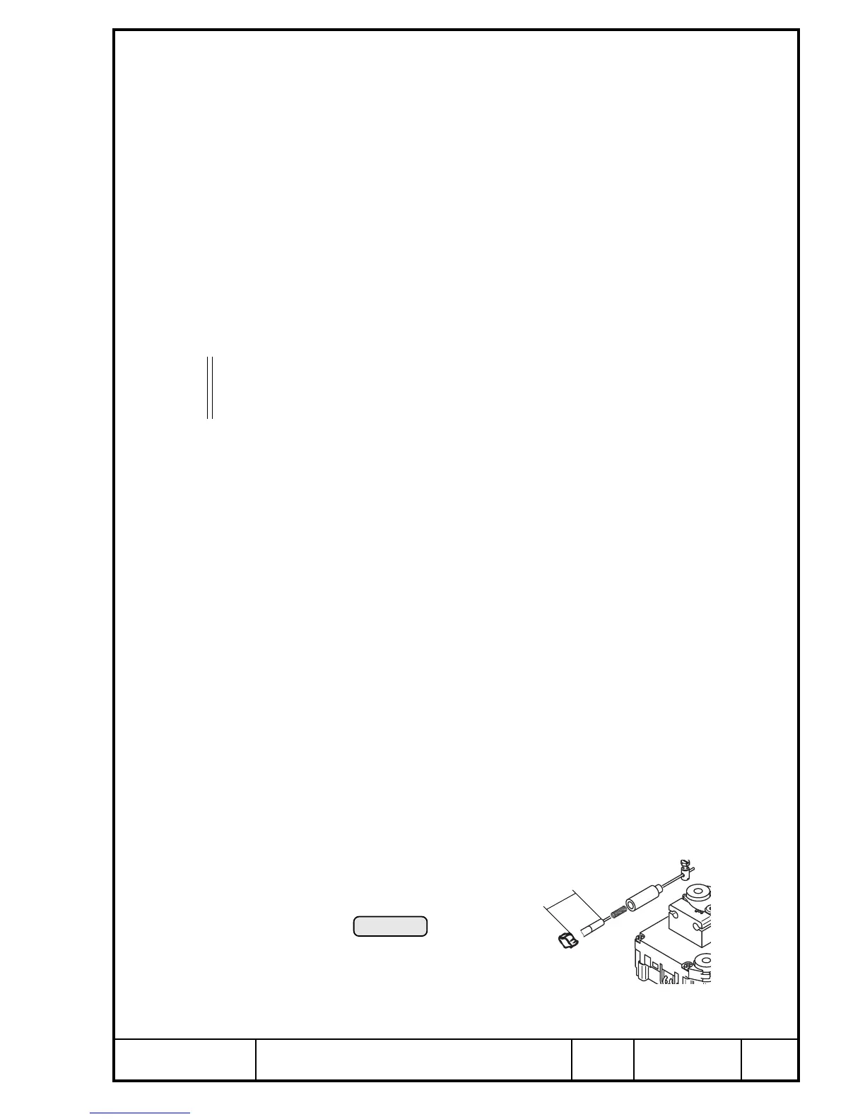
Whilst fitting the rope sheave interrupt the voltage supply to the TCU, or
unplug the 2-pole connection q. Risk of ruining the servo motor if it would
be activated by the TCU during assembly.
Fit rope sheave as per detail A, fig. 154 and secure with washer, lock washer
and Allen screw M5x20 O. The rope sheave has to be fixed to prevent
rotating of the output shaft when the rope sheave is tightened. Tighten to 6 Nm
(53 in.lb).
If the cable retainer has been removed at disassembly, apply LOCTITE 648
on cable retainer R and press it into servo motor housing.
Fit servo cable with pin U on waste gate lever and secure by cotter pin Y.
Feed wire rope through adjusting screw w and flexible conduit. Fit suitable
clamp y (e.g. crimp band clamp) for traction relief on servo cable as per fig.
154/1, using suitable tool. Insert pressure spring T into cable retainer R,
feed rope through spring and retainer around rope sheave and secure with
screw nipple E.
Adjust servo cable by M6 hex. nuts e such that no clearance is perceptible
on waste gate lever.
With this adjustment set, pre-tension the compression spring by 1 to 2 mm
(0,04 - 0,08 in.) at straightened cable with the adjustment screw at support.
Fit the Silicone tube 5x8 t into restoring spring.
Engage restoring spring on support and spring pin r.
■ ATTENTION: To minimize wear on spring engagement holes, engage
spring on spring pin, twist it by approx. one turn and engage
other end of spring on support.
Wire secure W between servo motor and traction relief such, that the servo
cable cannot escape from cable retainer and consequently changing the
setting.
fig. 154/1
25 mm
+5mm
02618

 Loading...


