ReferenceModification no.
- 0 -
Page
179
Date
1997 02 01
Main
914 F
01478
35
33
34
34
33
Pic. 143
41
00408
With the two Allen screws M6x20 r, lock washer A6 and hex. nut M6 re-
assemble, first only slightly tightening, the ignition coil bracket t, the ignition
coil bracket u, and the double ignition coils.
Insert ignition cable D into the ignition coil bracket F, and fit the double
ignition coils on rubber buffer e with the Allen screw w M6x16 and lock
washer.
◆ NOTE: When replacing the rubber buffer e, secure it with LOCTITE
221 on intake manifold.
Connect the white cables and the black grounding cables of the double
ignition coils without fail as per wiring diagram. Route the grounding cables
O and P towards outside. To achieve correct distance, fit the electronic
modules U on the ignition coil brackets with Allen screws Y M5x25.
Now all ignition coil fasteners can be tightened. Tighten ignition coil bracket
q and rubber buffer } with hex. nut M6 and lock washer.
13.4.14)Re-fitting of ignition electric set
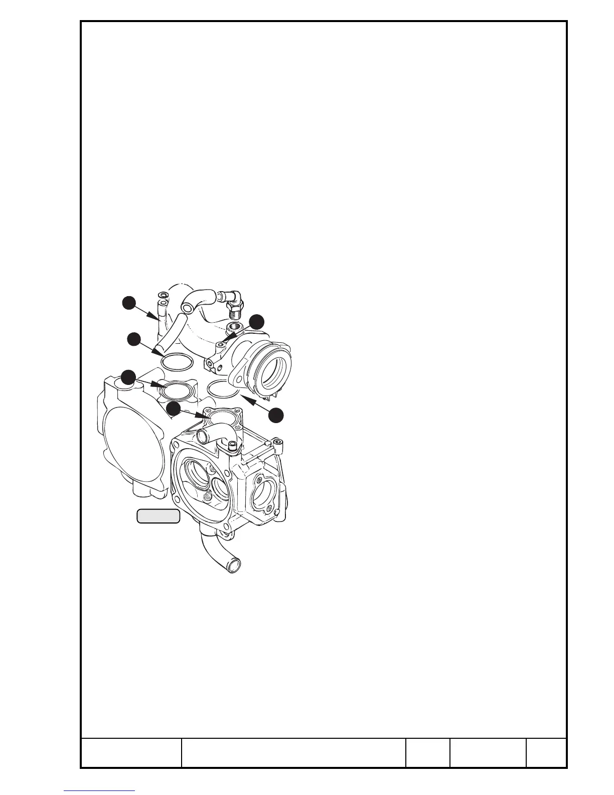
See Pic. 141 and 143.
Place O-rings L 34x2 into the groove : of cylinder heads
and remove the protections from the intake apertures. Fit
both intake manifolds a with pre-assembled ignition
electric set and tighten crosswise with 4 Allen screws
to 10 Nm (90 in.lb). Insert rubber buffer y into bracket
s of ignition housing and tighten with hex. nut and
lock washer.
Place distance sleeve d into position and fix ignition
electric set with hex. screw f M8, washer and lock
washer on crankcase. Now tighten all screws and
nuts of the ignition electric set.
Fit grounding cables O, P and S on boss j of
intake manifold with hex. screw I M6x16 and lock
washer. Attach both 4-pole plug connectors (elec-
tronic module to trigger set) and secure with cable
strap.
◆ NOTE: The trigger cable of ignition circuit A (top
module) is marked at the end of the
isolating hose with the colours blue and
red. Those of ignition circuit B (bottom
module) are marked with colours green
and colourless (neutral).
Connect the two red cables coming from the charging coils with the two pink
cables of the SMD electronic modules. Route the whole cable assembly into
the cable clamp and fit electronic module with Allen screw Y M5x25 on the
ignition coil bracket t.
■ ATTENTION: The cable shielding must be fully inserted into the cable
clamp to assure optimum mass connection.

 Loading...


