Reference
Modification no.
- 0 -
Page
80
Date
1997 02 01
Main
914 F
01476
11.8) Securing elements
See. Pic. 36
■ ATTENTION:Self-locking nuts, cotter pins, tab washers and safety wires must be
replaced each time they have been removed.
Respect without fail all additional indications regarding securing and sealing means
and lubrication of fixation elements. Adhere to specified tightening torques.
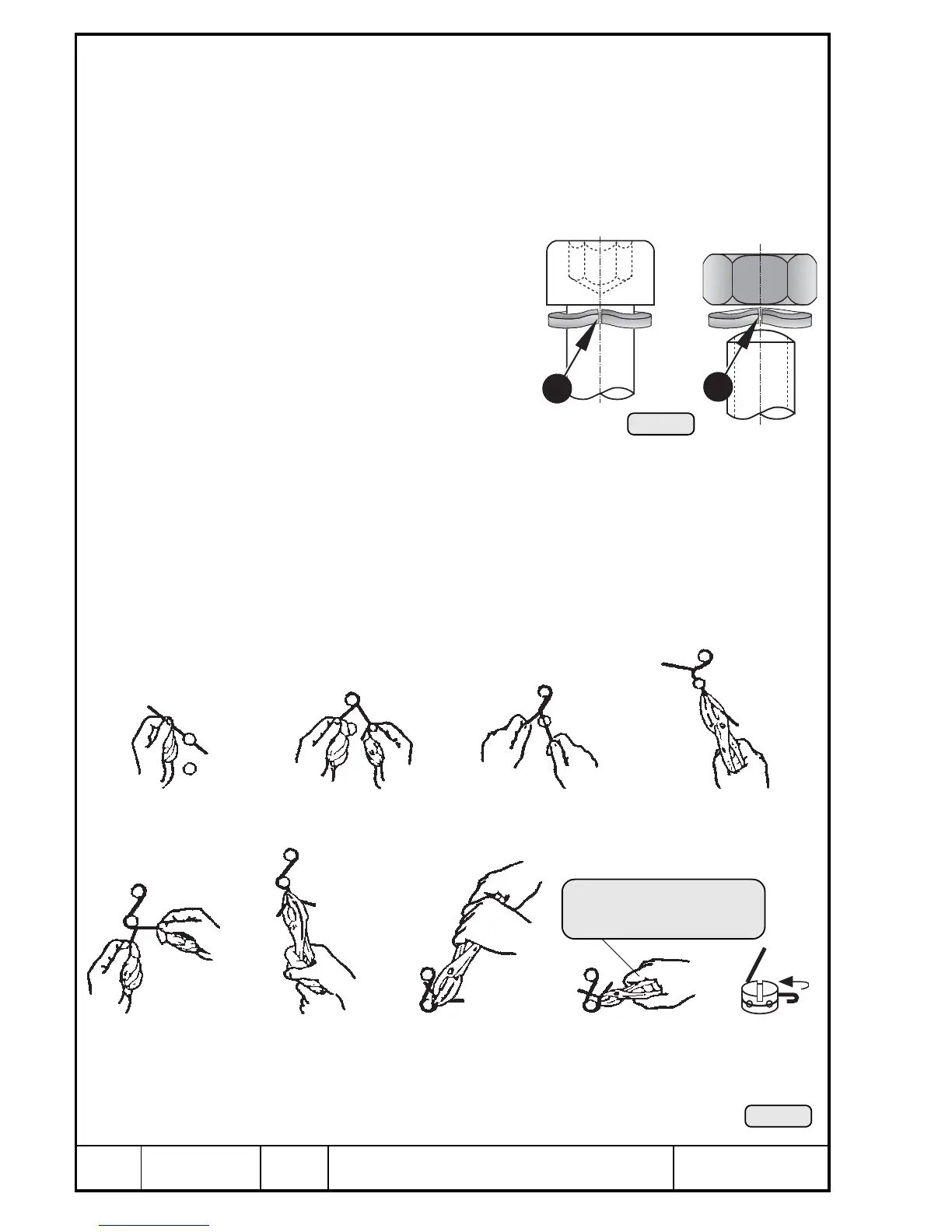
■ NOTE: Fit the lock washers with the
bent up ends Q facing the
screw head or nut.
11.8.1) Wire securing
See Pic. 36 and 37.
Safety wiring serves to secure screws
or nuts to prevent unintended loosen-
ing. The screws or nuts are secured by
a 0,8 mm (.0315 in.) safety wire twisted
3 to 4 turns per 10 mm (.4 in.). The wire
must by no means be overstretched.
▲ WARNING: As a principle, all external engine components and acces-
sories must be wire-secured for safety reasons.
Turn twisted wire
end around screw
Stretch wires
and twist
approx. 4 times
Twist wire several times
up to next screw
Pass through
safety wire
Wind wire end around
the screw
Pass wire through and
stretch it with pliers
FINAL CHECK
Safety wiring between screws
must not be loose!
Bend wire end
and press it
towards screw
Cut off excess
length or wire
Twist wire around
the screw
1
1
Pic. 21
Pic. 37
00144
00145

 Loading...


