Reference
Modification no.
- 0 -
Page
245
Date
1997 02 01
Main
914 F
01480
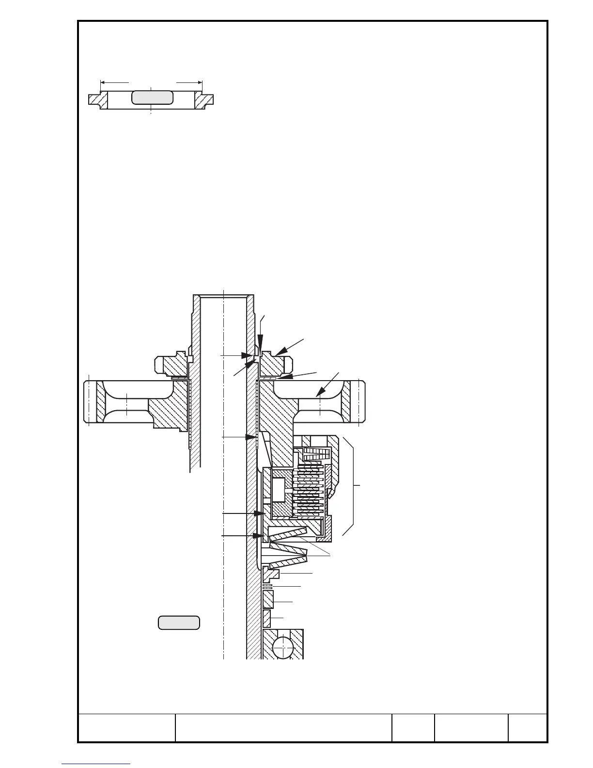
Turn gear cover. Next to fit are distance sleeve q 35,2/42/8 and eccenter w
for fuel pump. Then fit step collar e with dia. 40,8 mm towards disk spring, 2
disk springs r placed against each other and the 3
rd
disk spring t with it's
back to the previous disk spring. Take care that the disk springs rest
on the centering collar y of the hub. Apply LOCTITE Anti-Seize to
teeth of pre-assembled overload clutch u and slide into position on
propeller shaft. Carefully fit pre-oiled bearing bush i using circlip
pliers. Slide on dog gear o, plastic thrust washer p 33,2/51/1,2 coated on
both sides with LOCTITE Anti-Seize, and drive gear [.
■ ATTENTION: If the disk springs are not placed well centered, the dog gear
cannot be depressed sufficiently to allow inserting of ring
halves. Do not increase the pressure, but disassemble the
clutch again and center the disk springs more accurately.
◆ NOTE: Coat contact surfaces of disk springs and dogs as well as the
tooth profile of propeller shaft with LOCTITE Anti-Seize.
14.4.14)Adjustment of disk spring pre-tension
See Pic. 240 and 227.
With springs in the released state,
the face ] for the ring half must
be in line with the upper edge A
of the groove in propeller shaft.
Compensate the difference by
shims S placed without fail be-
tween eccenter w and step col-
lar e.
After pre-tensioning of disk
springs, depress gear o with
assembly ring, part no. 876 885,
until the ring halves can be in-
serted. Insert ring halves. Re-
lease disk springs (see also
Chapter 14.4.10).
■ ATTENTION:Never depress
springs flat, otherwise clutch
drum of overload clutch will dam-
age the gear cover. The ring
halves must be completely in-
serted in the groove on propeller
shaft!

 Loading...


