Reference
Modification no.
- 0 -
Page
251
Date
1997 02 01
Main
914 F
01480
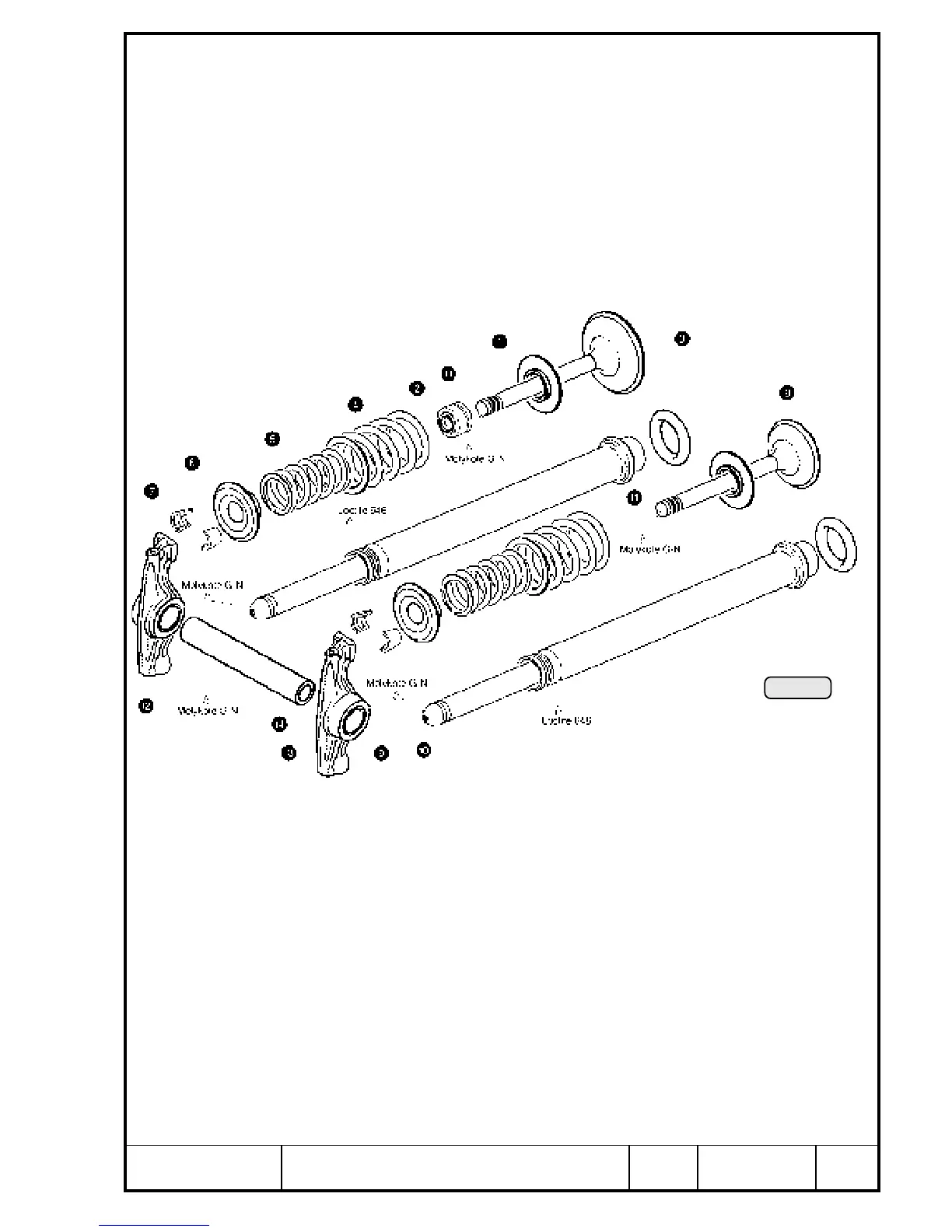
14.5.7) Re-assembly of cylinder head
See Pic. 254.
Place valve spring support Q in position and fit new valve stem seal W on
inlet side only. Insert pre-oiled inlet valve E from outside into valve guide,
place both valve springs (outer R and inner T) and spring retainer Y in
position. Compress valve springs by utilizing fitting jig and clamp. Insert valve
cotters U and release springs (see Chapter 14.5.1). Apply same procedure
for outlet valve I.
◆ NOTE: Ensure correct positioning and equal gap of valve cotters.
Apply MOLYKOTE G-N on rocker arm bore O, push rod head P, and valve
contact surface {. Position inlet rocker arm } and outlet rocker arm q, apply
MOLYKOTE G-N to both ends of rocker arm shaft w and push it into bearing
support, see Chapter 11.7.5).
◆ NOTE: The rocker arm bearing support is a slide fit. Do not act with
force!
Lubricate all moving internal parts with engine oil (see Chapter 11.7.1,
13.2.10 and 13.2.11).
Pic. 254
00289

 Loading...


