ReferenceModification no.
- 0 -
Page
127
Date
1997 02 01
Main
914 F
01478
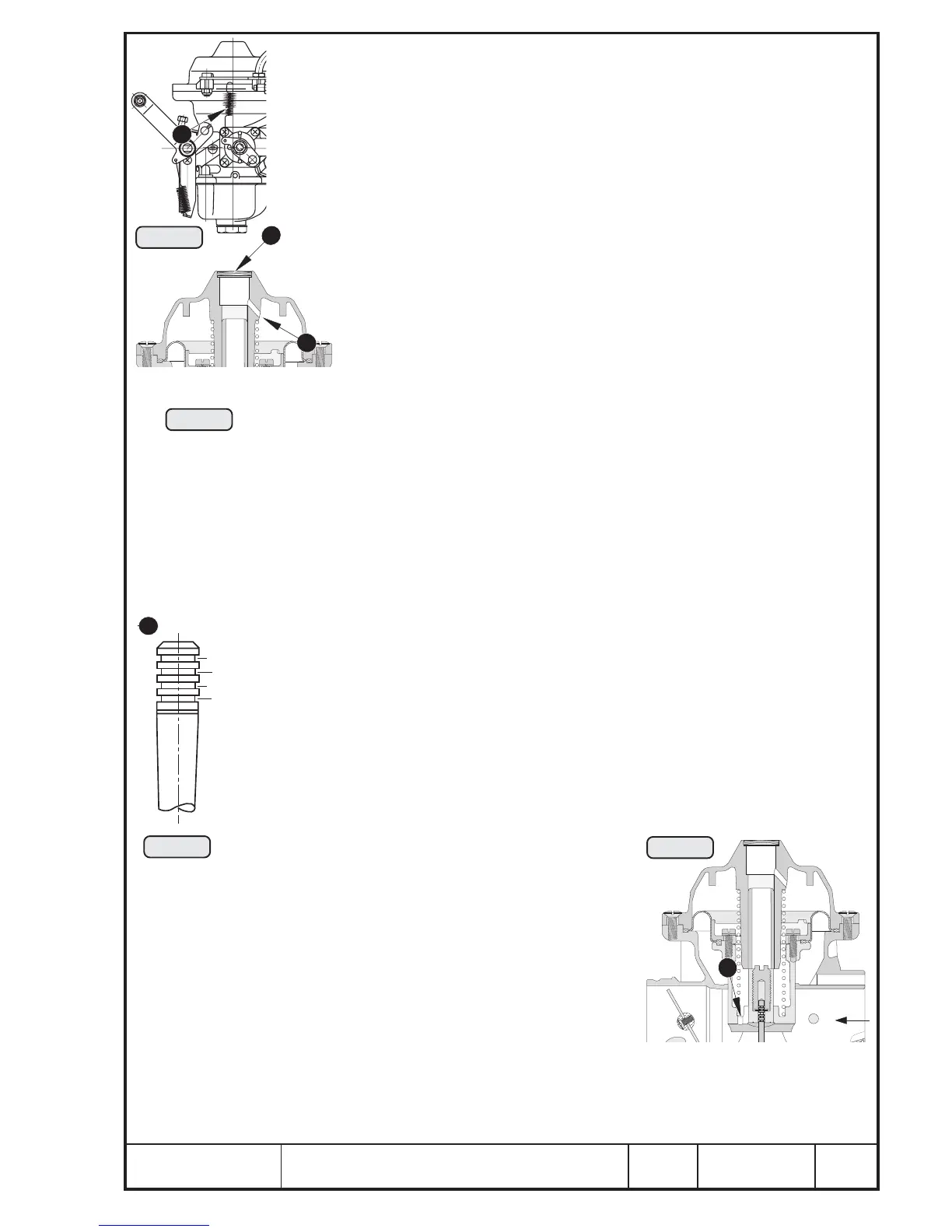
13.1.2.4) Diaphragm
See Pic. 63/64 and 65.
Unhook spring Q of choke from start lever W and chamber top E.
◆ NOTE: The diaphragm R is linked to the plunger (carburetor
piston). Depending on the pressure prevailing, the plunger
is moved up or down.
For checking, remove the 2 countersunk screws T M5x12 and Allen screw
Y M5 along with nut and shim, remove the chamber top E and the spring
U. Check tight fit of the cover I on chamber top.
Wash chamber top with cleaning agent and blow the inside
venting bore O with compressed air, then check visually. See Pic.
65.
◆ NOTE: The diaphragm R is fixed by the retaining ring P to
the carburetor piston {.
Remove plunger from the carburetor housing and remove 4 Allen screws }
M4x12.
■ ATTENTION: The position of the carburetor piston is controlled via the
diaphragm. On the diaphragm there are 2 positioning
noses. The nose q fits exactly in the recess in the plunger,
nose w must engage in the recess in the carburetor hous-
ing.
Check diaphragm for cracks or brittleness, replace if necessary.
13.1.2.5) Jet needle, carburetor piston
See Pic. 63/66 and 67.
The jet needle e controls the fuel consumption at part load. It may be
regulated by choosing position of jet needle between 1 and 4.
Modifications are allowed only after consultation with the engine manufac-
turer.
◆ NOTE: A higher position causes "deeper plunging" of the jet
needle into the needle jet r ➍ smaller flow diameter ➍
leaner mixture.
Lower position ➍ richer mix-
ture.
Remove fixation screw t and check jet nee-
dle e with circlip y for wear. Pay special
attention to the grooves and the taper of the
needle. At visible wear the jet needle must be
exchanged and refitted in the same position.
■ ATTENTION: The jet needle fitted must
move freely.
Visually check outside of plunger { and the
two inside compensation bores u.
00032
Nadelposition
(needle position)
1
4
3
2
00033
Pic. 65
Pic. 66
00032
Pic. 67
1
00025
Pic. 64
8
9
15
19

 Loading...


