Reference Modification no.
- 0 -
Page
152
Date
1997 02 01
Main
914 F
01478
13.3) Cooling system
Besides the maintenance work prescribed in Chapter 12) and description of the
cooling system, Chapter 9.1) further maintenance work is described as follows:
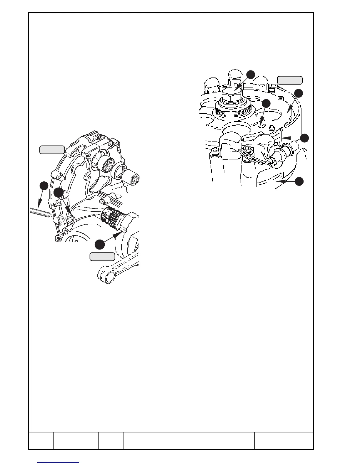
13.3.1) Water pump removal
See Pic. 105 and 106.
The water pump is integrated in the igni-
tion housing. For maintenance work
the magneto hub Q and the magneto
housing W have to be removed. On
some engine installations this re-
quires removal or partial lifting of
engine.
To remove the hex. screw
E M16x1,5 from the fly-
wheel hub, it is an ad-
vantage to lock the
crankshaft. This is
possible with crank-
shaft locking screw R,
part no. 240 880, see
„Special Tools“!
Remove the plug screw on the left crankcase half T. Turn
crankshaft for cylinders no. 1 and 2 to Top Dead Centre
position. Lock with crankshaft locking screw R. To facilitate
finding of this position, turn crankshaft to have the 4-digit
number Y cast in the flywheel hub Q align with the edge U
of the ignition cover. Insert crankshaft locking screw into
crankcase. Turn crankshaft with a ring wrench slightly to
and fro until the locking screw engages in the recess I of
the crankshaft, and tighten to 10 Nm (90 in. lb).
Pic. 106
6
2
4
5
Pic. 104
8
Pic. 105
3
7
1
00375
00376
00344

 Loading...


