ReferenceModification no.
- 0 -
Page
165
Date
1997 02 01
Main
914 F
01478
▲ WARNING: Proceed with particular care because the ignition is not
switched off.
— Assure sufficient ground connection between engine, battery and fuse-
lage. Respect the wiring diagram of the aircraft manufacturer.
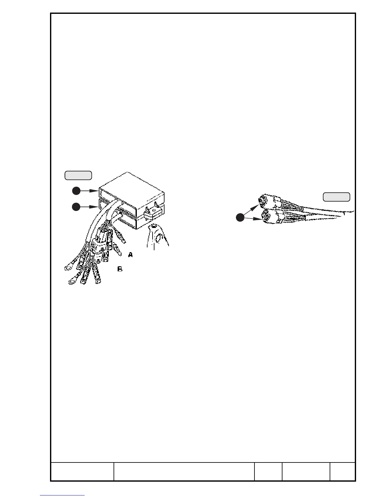
13.4.3) Electronic module, trigger set
See Pic. 131 and 132.
■ ATTENTION: If one ignition circuit fails, do not interchange the 2 4-pole
plug connectors Q of trigger cables for failure tracing.
Contrary to ROTAX engine 912 the ignition timing for circuit
A and B are different!
It, however, is possible to interchange the modules W as they are identical.
If the failure remains with the ignition circuit, either the electronic module or
the charging coil on the stator is the cause. If renewal of the respective
electronic module does not help, the charging coil is defective. Remove and
renew the stator, see Chapter 13.4.16).
Pic. 131
A
2
2
Pic. 132
1
00399
00398
If the failure passes on with the ignition circuit, the triggers of the respective
ignition circuit are the cause. In both cases the disassembly work described
below is necessary, see Chapters 13.4.12 through 13.4.15).

 Loading...


