Reference Modification no.
- 0 -
Page
178
Date
1997 02 01
Main
914 F
01478
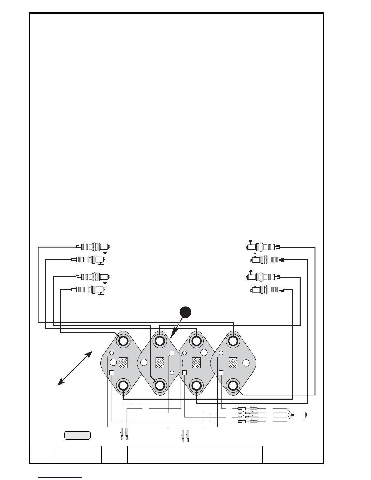
2B
2T
4B
4T
1B
1T
3B
3T
2B
2T
4B
4T
1B
1T
3B
3T
ws
ws
sw
sw
sw
ws
ws
sw
B = unten / bottom
T = oben / top
ws = weiß / white
sw = schwarz / black
sw
sw
sw
sw
A
B
A
B
Propellerseite /
propeller side
Magnetseite /
magneto side
Pic. 142
23
00407
Renewal of double ignition coils
At renewal of a double ignition coil, the following dismantling procedure is
required:
Remove hex. nut M6 { and rubber buffer } with bracket q. Remove the
Allen screw M6x16 w from rubber buffer e with an Allen key. Remove both
Allen screws r and ignition coil bracket t as well as the 3
rd
rubber buffer y
with bracket u.
Remove both Allen screws M6x30 i from the distance nut M6 o. After
detaching the double grounding cables P, the double ignition coils p can be
replaced individually. The ignition cables are screwed in and therefore are
renewable.
◆ NOTE: Except the double ignition coil [ for spark plug 3 and 4
bottom, all are fitted in the same position, with boss ]
upwards.
13.4.13)Re-assembly of ignition electric set
See Pic. 141, 142
Re-assembly of double ignition coils in reversed sequence.
Attach the double ignition coils offset and in the correct position as per
illustration, with the two Allen screws M6x30 i and lock washers A6 with
distance nut M6 o. Pay attention to the double ignition coil [ for spark plugs
3B and 4B. It must be fitted turned by 180°, compared with the 3 other double
ignition coils (see Pic. 105).

 Loading...


