Reference Modification no.
- 4 -
Page
142
Date
2002 01 01
Main
914 F
01478
13.2) Lubricating system
Besides the maintenance work prescribed in Chapter 12) and description of the oil
circuit in the engine in Chapter 9.3) further work for maintenance is described as
follows:
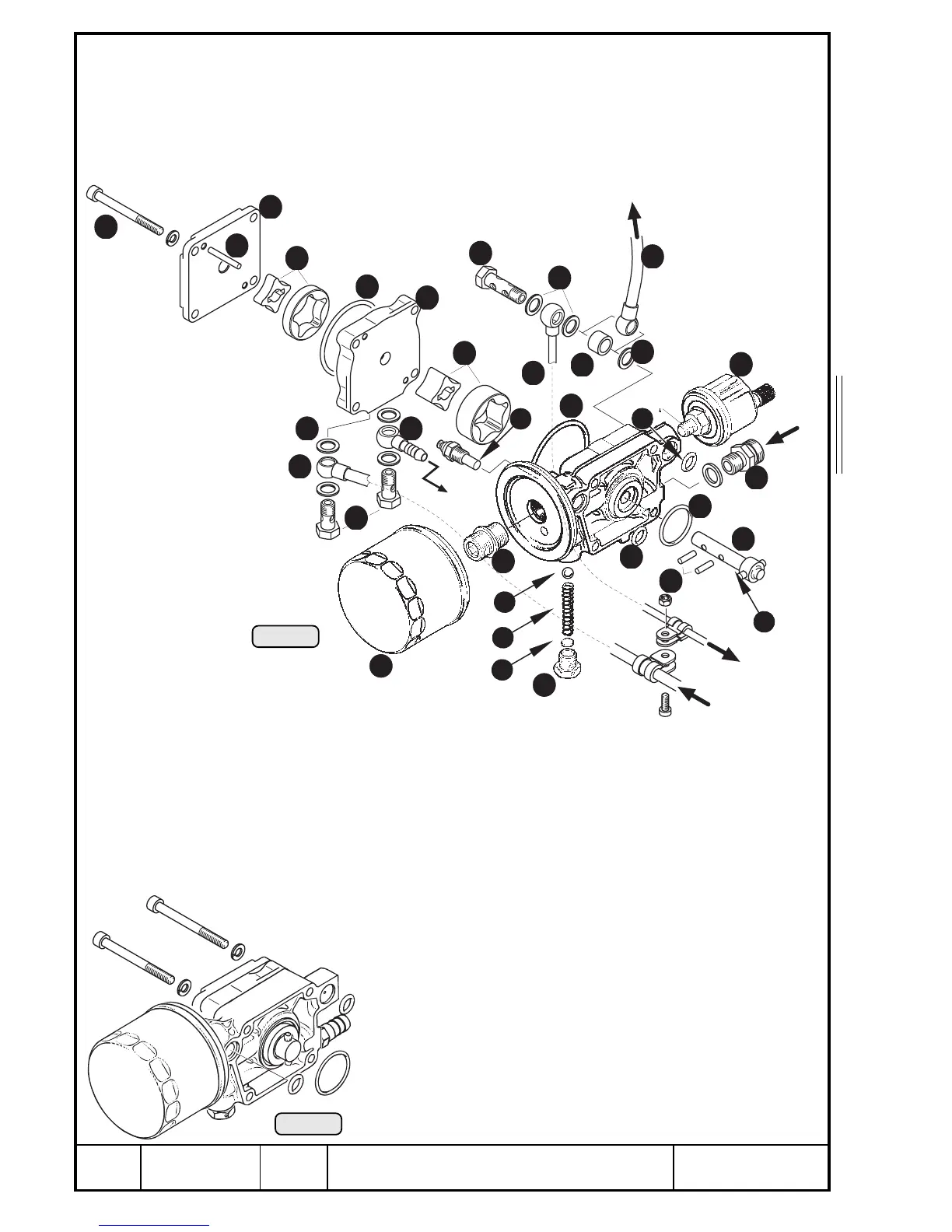
13.2.1) Oil pump
13.2.1.1) Oil pump removal (main- and suction oil pump)
See Pic. 91 and 92.
Drain oil.
Remove oil tube from screw socket Q (inlet). Remove both banjo screws W
from suction pump and sealing rings E.
◆ NOTE: The suction oil tube R and the hose nipple T
need not be removed.
Remove banjo screw Y and 3 sealing rings U. Also remove
the spacer I (versions F2 / F4). On version F3 the pressure
oil tube O towards propeller governor should be removed for
easier disassembly. Same procedure on pressure oil tube P
towards turbo charger.
Remove oil filter { with strap spanner, part no. 877 620.
Remove 4 Allen screws } M6x65 with lock washers and the
oil pump ass’y with 2 O-rings 11x2,7 q and 1 O-ring 30x2,5
w.
00072
Pic. 92
0-10
bar
zum hydr. Verstellregler
to hydr. governor
Ölzulauf
oil inlet
zum T urbolader
to turbocharger
vomT urbolader
from turbocharger
zum Öltank
to oil tank
Loctite 603
Pic. 91
05020
12
22
28
9
8
7
6
24
25
27
15
5
11
2
3
4
10
14
17
1
13
26
30
18
16
19
20
21
13
23
29
31
7

 Loading...


