Reference
Modification no.
- 0 -
Page
32
Date
1997 02 01
Main
914 F
01476
AUX MAIN
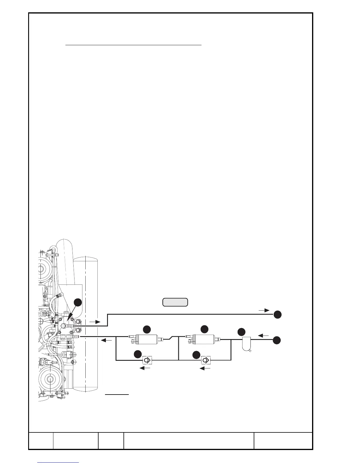
9.2) Fuel system
See Pic. 11.
The fuel system comprises the following items:
➪ fuel tank
➪ coarse filter
➪ water trap
➪ fire cock
➪ 2 electric fuel pumps
➪ 2 check valves
➪ and the required fuel piping and connections
The fuel flows from the tank via a combination of filter and watertrap Q to the two
electric fuel pumps (W and E), connected in series, passes on to the fuel pressure
regulator T and further on to the individual carburetors.
Parallel to each fuel pump a separate check valve R is installed.
◆ NOTE: The arrangement of the two fuel pumps connected in series yields
better reserves against vapour formation at high altitudes and tem-
peratures.
The two check valves in the system are necessary to warrant trouble
free operation of the fuel system with one pump only.
Via the return line U the surplus fuel passes from the fuel pressure regulator back to
the tank or to suction side of fuel system.
◆ NOTE: The fuel pressure regulator serves to maintain the fuel pressure
always approx. 0,25 bar (3,6 p.s.i.) above the changing boost pres-
sure in the airbox thus warranting proper operation of the carburetor.
Legend:
Q coarse filter / water trap
W main fuel pump
E auxiliary fuel pump
5
4
2
3
7
6
1
R check valve
T fuel pressure regulator
Y feeding line from tank
U return line to tank
Pic. 11
00103
4

 Loading...


