Reference Modification no.
- 0 -
Page
136
Date
1997 02 01
Main
914 F
01478
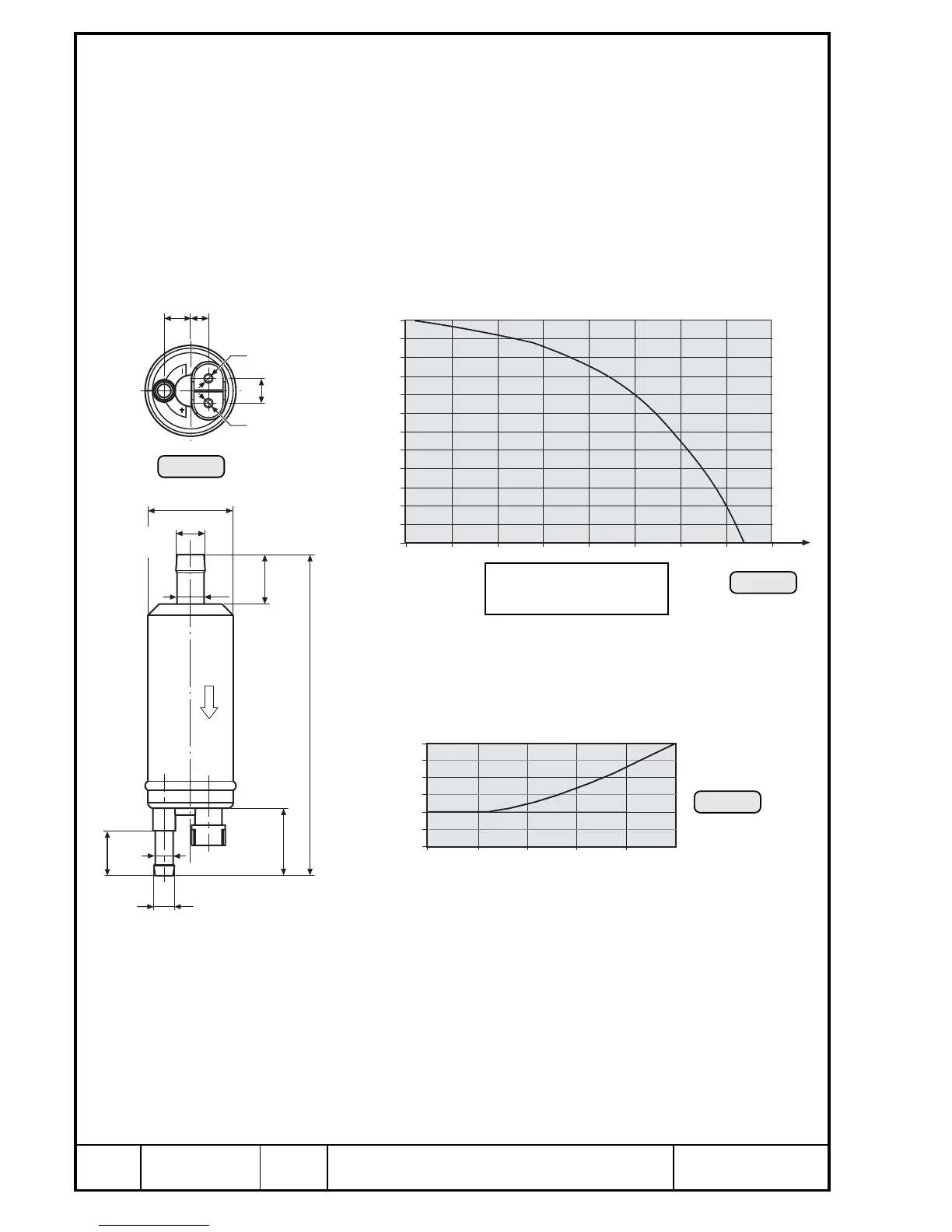
13.1.10)Fuel pump
See Pic. 83/84 and 85.
The fuel pumps are maintenance-free and need no adjustment or servicing.
Visually check the fuel pump.
■ ATTENTION: The fuel pump must not be disassembled, there are no
spare parts available. If necessary, renew the complete fuel
pump.
In case of troubles, check function via the fuel supply and/or current input.
Flow rate / pressure: See diagram Pic. 84.
∆P= P2 – P1
The diagram shows the flow rate of the electric fuel pump in
relation to pressure.
Current input / pressure: See diagram Pic. 85.
Take care of the following:
➪ The diagrams show the minimum limit curve at nominal voltage (12V DC)
of the pump.
➪ Pressure indications in Pic. 84 and 85 refer to boost pressure.
➪ Pressure and suction height are "ZERO".
➪ The graph applies only to a seasoned pump: Run-in period approx. 30
minutes.
◆ NOTE: The pump may increase its performance by approx. 20 %
after running-in.
ø38
ø13,3
ø12
ø9

 Loading...


