Reference
Modification no.
- 0 -
Page
233
Date
1997 02 01
Main
914 F
01480
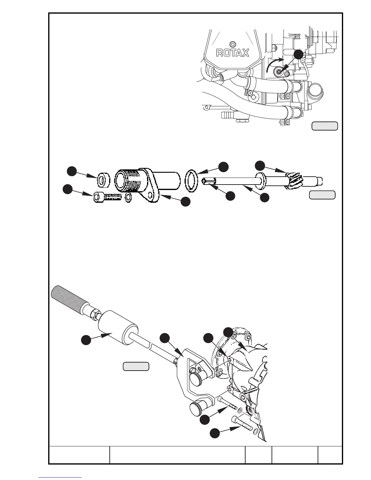
14.3) Rev. counter drive
See Pic. 208 and 209.
Drive of the mechanical rev. coun-
ter Q offered as optional extra via
the worm gear pressed into the
camshaft.
Remove Allen screw M5x16 W and
lock washer and withdraw rev.
counter housing E along with O-
ring R and rev. counter shaft T
from ignition housing (see Chapter
13.3.9).
Inspect teeth Y and square end U
of rev. counter shaft. At oil leakage renew oil seal I 6x11x3 resp. O-ring R. Press in
new oil seal fully home to stop in housing using punch, part no. 877 680.
14.4) Propeller gearbox
See Pic. 210, 211, 213 and 214.
Before removing the gearbox it is useful to check the slipping torque (see Chapter
12.4.2).
Remove 8 Allen screws Q M6 and 2 Allen screws W M8 crosswise from gear cover
E. The gear cover is kept in position by 2 dowels. Screw puller R, part no. 877 660,
onto M8 taps T of gear cover E. Now the complete gearbox can be pulled off with the
impact puller Y without damaging the ball bearing and the propeller shaft.
Pic. 208
4
Pic. 209
1
4
6
5
7
3
8
2
Pic. 210
1
2
3
4
5
6
00244
00243
00241

 Loading...


