ReferenceModification no.
- 0 -
Page
153
Date
1997 02 01
Main
914 F
01478
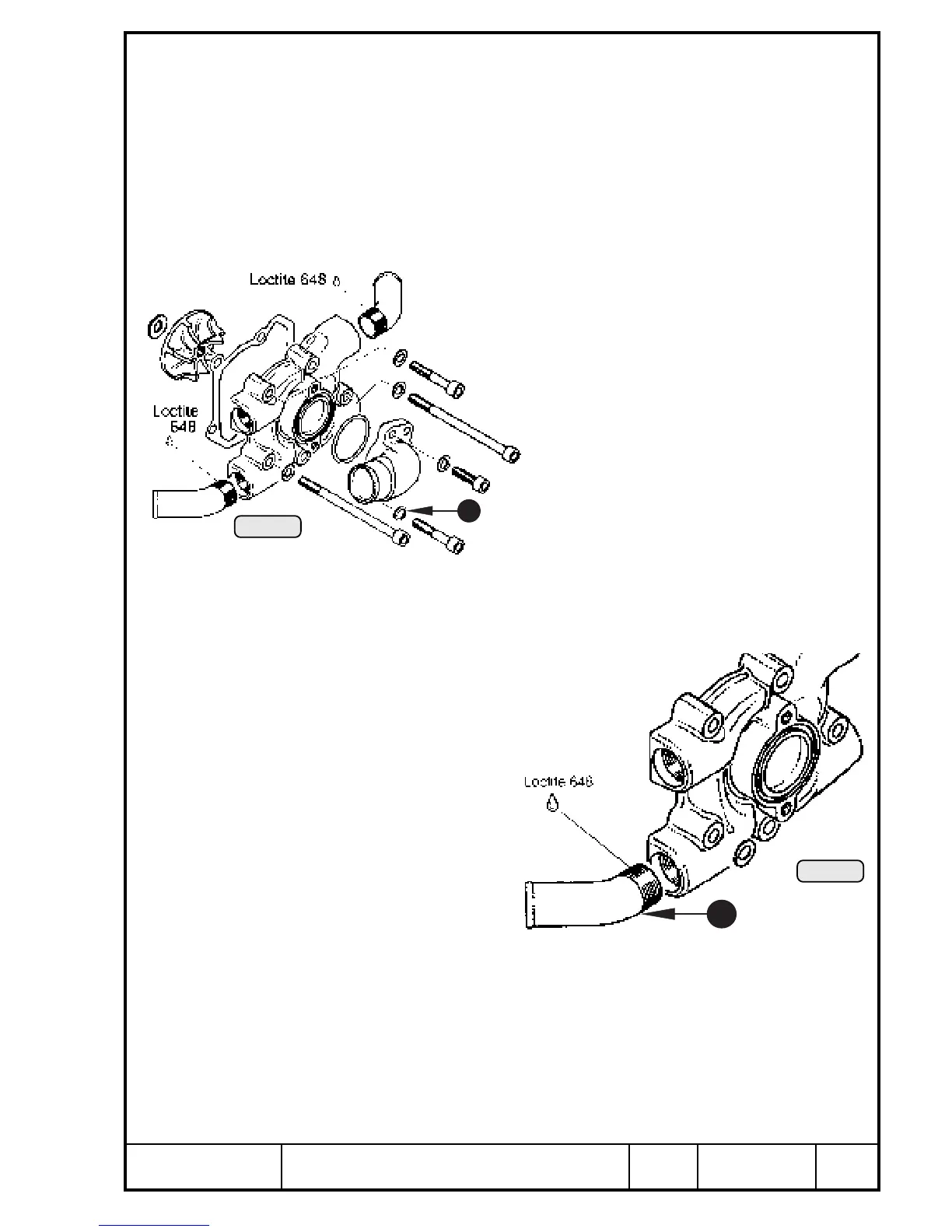
13.3.2) Water pump housing - disassembly and check
See Pic. 107 and 108.
Remove the 2 Allen screws M6x20 Q of the water inlet elbow W and remove
elbow with O-ring.
◆ NOTE: Register the position of the inlet elbow!
Remove the 4 hose clamps from water drain hoses and from water pump
housing. By removing 5 Allen screws M6 E the water pump housing R with
gasket T can be taken off.
■ ATTENTION: The Allen screw Y goes through to the
water chamber and therefore is sealed
with sealing ring U.
Check inside for traces of possible contact with impeller
I. The necessary clearance can be achieved by
axial spacing of the water pump shaft. The shim O
fitted behind the impeller is of stainless steel.
Remove the impeller I with special tool, part
no 877 295, with crankshaft locked, turning
counter-clockwise.
Check the bent water socket P screwed into
the water pump housing for leakage, cracks
and tight fit, replace if necessary. Mark the
position of the bent socket. Warm up water
pump housing to approx. 80° C (180° F) and remove the socket. Clean
threads carefully from LOCTITE remains, apply LOCTITE 648 to the new bent
water socket and fit it into position after 5 turns.
Pic. 107
I
T
R
7
E
W
O
Y
E
Q
Pic. 108
10
00377
00378

 Loading...


