Reference
Modification no.
- 0 -
Page
244
Date
1997 02 01
Main
914 F
01480
16
14
15
17
18
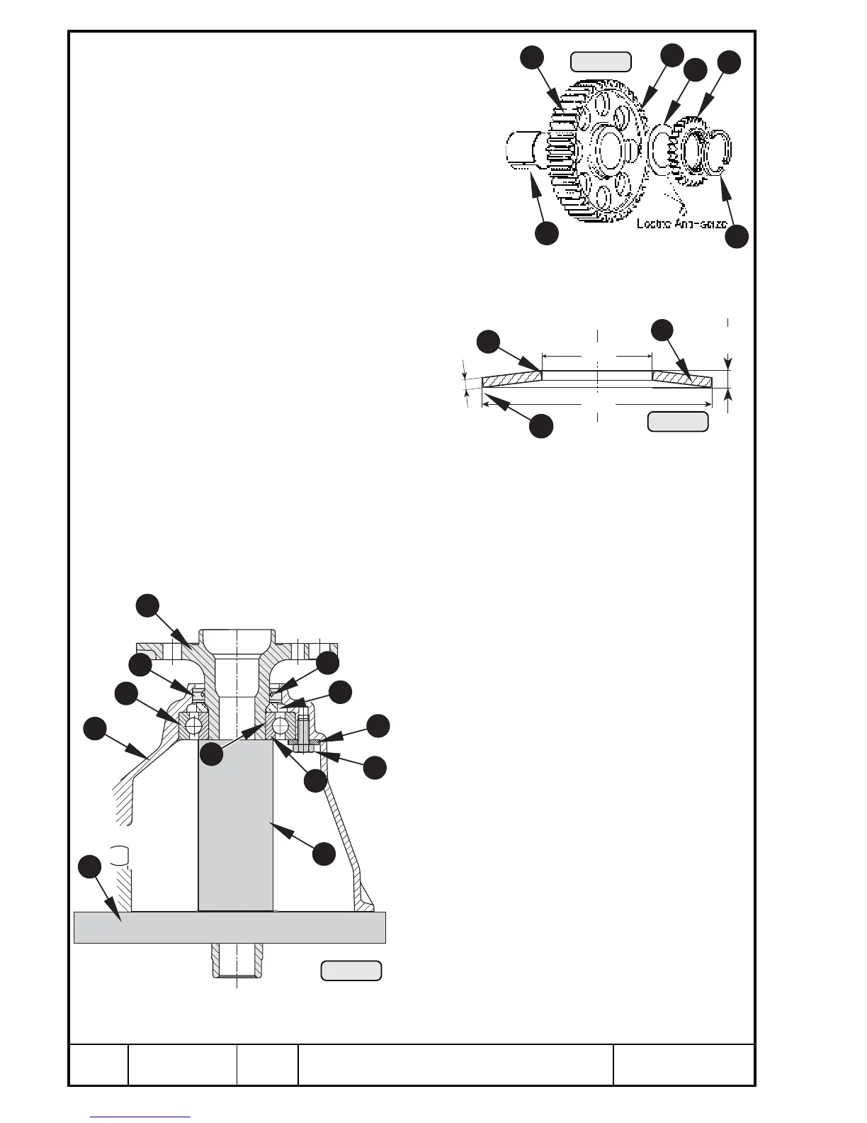
Pic. 236
11
➪ Check teeth w of gear set.
➪ Inspect eccenter for fuel pump and
fuel pump plunger for wear, see
Chapter 13.1.7).
➪ Check step collar for wear in the
area of disk spring contact surface.
➪ Measure plastic thrust washer r
between dog gear { and drive gear
e, see dimension t in Chapter 15).
➪ Check dog gear bush t of hardened
steel for wear.
➪ Visually check ring halves y, renew as required.
➪ At visible wear of disk springs
u in the contact area i they
have to be renewed. Check
dimension y of the released
disk spring, see Chapter 15).
Dimensions of new
wear limit
See Wear Limits, Chapter 15).
14.4.13) Gearbox — Re-assembly
See Pic. 238, 239 and 240.
Heat gear cover Q with hot air gun to approx. 100° C (215° F). Insert oil seal
W 40-55-7 from the inside, using punch, part no. 876 518, and grease sealing
lips E. Add distance ring R 36/50/5,5 with rounded side towards oil seal.
Press in ball bearing T, utilizing press-ring, part no. 877
320 and insertion punch, part no. 877 275. Fix bearing
in position, using 4 hardened washers Y 7,2/18,8/3
and hex. screws U M7x16.
◆ NOTE: Secure screws with LOCTITE 221 and
tighten to 10 Nm (90 in.lb).
Place gear cover on a suitable plate I with a bore
for propeller shaft. Apply LOCTITE Anti-Seize to
bearing seat P 35 mm (1,4 in.) dia. and press
propeller shaft O carefully from outside into gear
cover.
■ ATTENTION: Do not tap!
Make absolutely sure to support the inner ring { of
the bearing with suitable tube }. It is an advan-
tage if gear cover is still warm at this stage.
9
2
5
1
3
4
6
7
8
10
11
12

 Loading...


