800
600
400
200
0
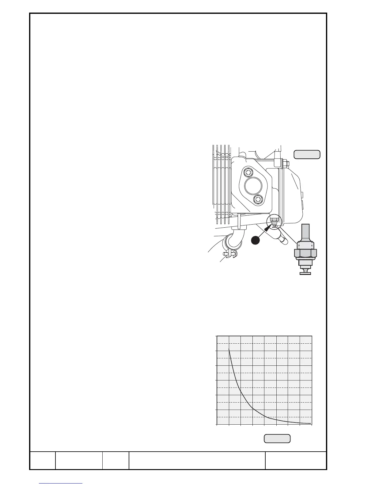
Pic. 193
00327
13.7) Temperature- and pressure observation
Besides the special checks, see chapter 12.4 and description of the systems find
further maintenance precedures as follows.
◆ NOTE: Several temperature control points are located on the Rotax engine
914 F. Refer to wiring diagram in Maintenance Manual.
13.7.1) Cylinder head temperature sensor
See Pic. 192 and 193.
The two temperature sensors Q are screwed into position on underside of
cylinder head 2 and 3. At cylinder head temperature observation only
temperature of cylinder head material but not of coolant is taken. The max.
operating temperature must not be exceeded. At a rise above the limit check
the following.
— cooling system
— temperature sensor
— indicating instrument
— wiring connections
— sensor cable
At engine operation with 100% anti-
freeze concentrate (without adding
water) possible formation of residues
near sensor might result in too high
temperature indication. Adding of
approx. 20% water will rectify this
fault.
◆ NOTE: Grounding connec-
tion of the sensor
direct via the cylinder
head.
For sensor resistance see graph below of sensor resistance over tempera-
ture.
deviation: max ± 10%
At installation secure temperature
sensor with LOCTITE 221 and
tighten to 10 Nm (90 in.lb).
00327

 Loading...


