Reference
Modification no.
- 0 -
Page
237
Date
1997 02 01
Main
914 F
01480
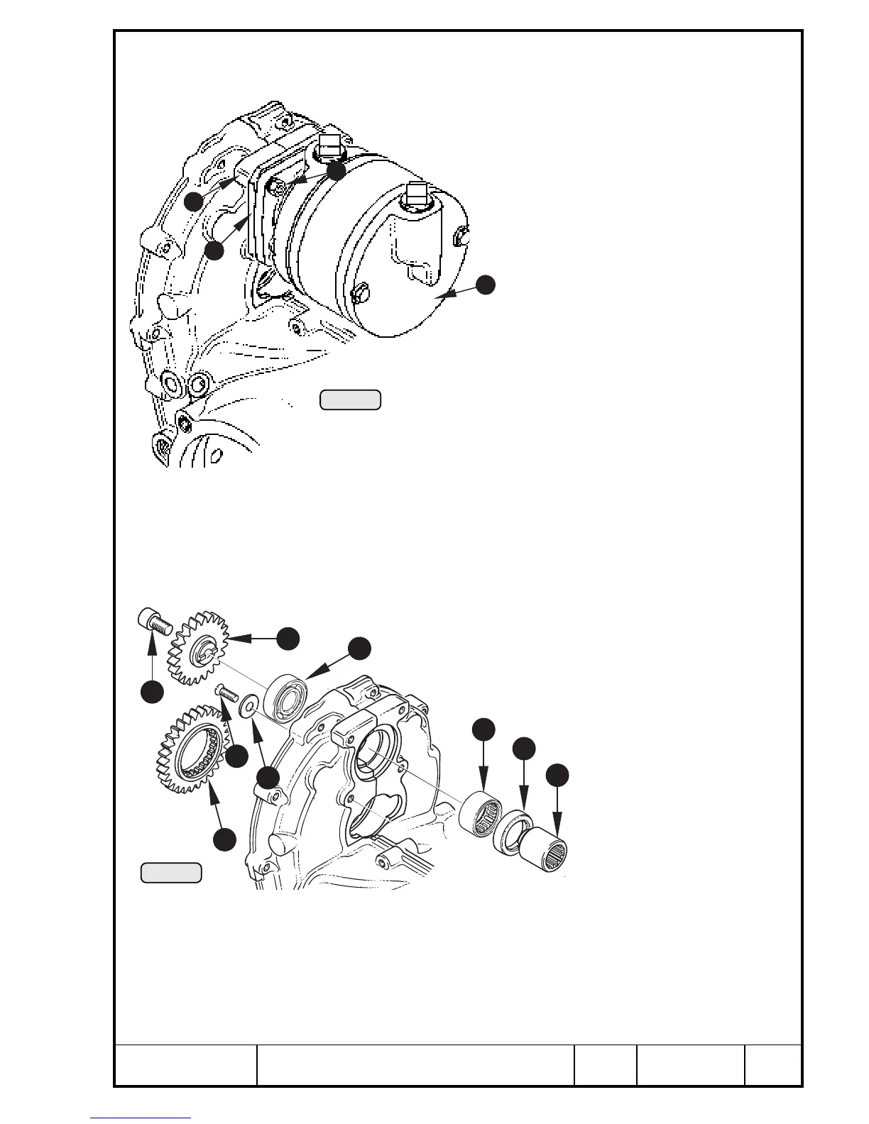
14.4.4) Vacuum pump - removal
See Pic. 218.
Remove 4 hex. nuts Q M6 and lockwashers and with-
draw vacuum pump W from crankcase R along with
gasket and attachment flange E.
14.4.5) Drive of vacuum pump - removal
See Pic. 219.
Drive of vacuum pump via drivegear Q fitted on propeller shaft. Reduction
ratio 22 : 29.
Check ball bearing W and needle sleeve E. Check toothing of
drive gear Q, vacuum pump gear R, drive sleeve T and
drive shaft of vacuum pump.
If the ball bearing or needle sleeve must be
renewed, remove the vacuum pump as
follows:
Lock drive sleeve T with
holder, part no. 242 660, re-
move Allen screw Y M8x14
and withdraw vacuum pump
gear R with drive sleeve T.
Remove countersunk screw
U M5x12 with washer I for
ball bearing fixation.
Remove oil seal O and
press out needle sleeve and ball bearing with suitable step punch towards
propeller flange. Clean and inspect bearing seat.
◆ NOTE: At this procedure the needle sleeve Q, oil seal O and ball
bearing E are damaged and must be renewed.
7
Pic. 218
4
1
2
3
5
9
3
2
4
6
1
Pic. 219
8
4
00252
00251

 Loading...


