resistance
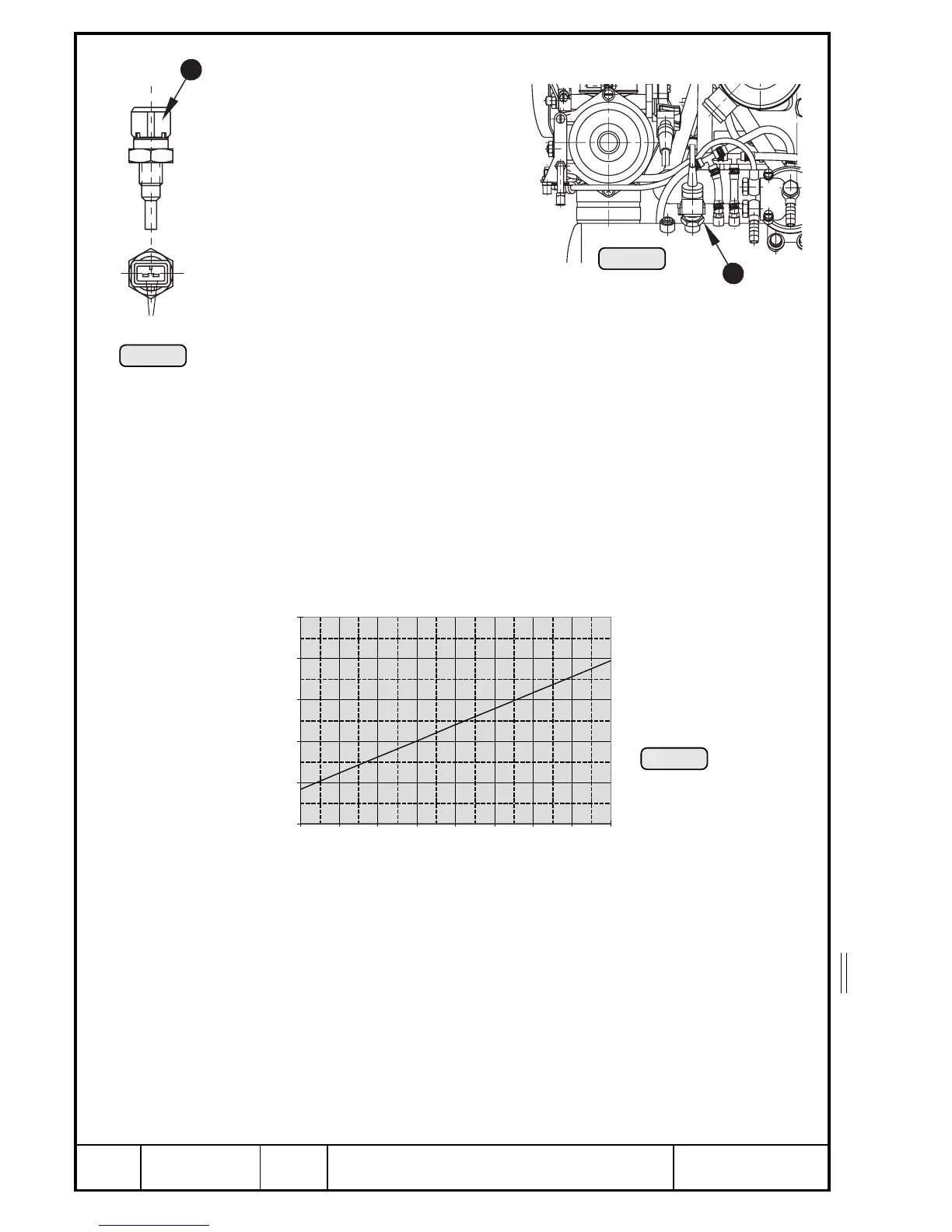
13.6.2.4) Resistance thermometer (Intake air temperature sensor)
See Pic. 181,182 and 183.
The sensor Q for measuring intake
air temperature is screwed into
airbox.
1
00055
00056
3
W
1
Pic. 181
Pic. 182
Pic. 183
➪ Inspect for physical damage
➪ Measuring of the resistance:
- sever plug connection to wiring harness and re-establish connection
straight after readings were taken and verify tight fit of plug and engage-
ment of catch
- measure resistance between the two terminals W and compare with
relevant resistance/temperature chart below.
Allowance for resistance: max ±1%
■ ATTENTION: At physical damage or readings outside allowance ex-
change sensor without delay.
At fitting of the resistance thermometer secure with LOCTITE 221 and tighten
to 15 Nm (135 in.lb).
00223

 Loading...


