Reference Modification no.
- 0 -
Page
148
Date
1997 02 01
Main
914 F
01478
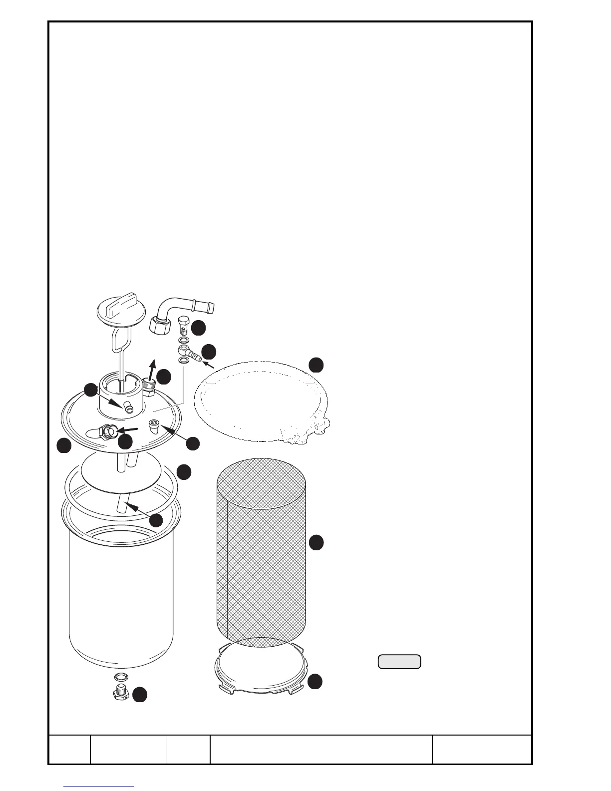
13.2.6) Oil tank
See Pic. 101.
Detach oil tubes. Remove banjo screw Q M10 and hose nipple W with
sealing rings 10x14.
Loosen profile clamp E and remove oil tank cover R with O-ring T.
Disassemble internal parts of oil tank like baffle insert Y and partition U.
Remove oil drain screw I and sealing ring 10x18 w.
Clean all parts.
Check oil inlet O, oil outlet P (towards oil cooler/oil pump), venting nipple
{, oil return } (turbo) and suction tube q for free passage and for damage.
Visually check all parts of oil tank.
Re-assembly of oil tank in reversed sequence of disassembly.
Fit oil drain screw M12x12 with new sealing ring, tighten to 25 Nm (225 in.lb).
Secure with safety wiring.
Tightening torque of banjo screw Q
17 Nm (150 in.lb).
▲ WARNING:
After re-installation of the engine en-
sure no air is trapped in the lubrica-
tion system. For correct procedure,
see Chapter 13.2.10).
00077
Pic. 101
13
3
1
8
5
7
6
10
9
12
2
4
11

 Loading...


