Reference
Modification no.
- 0 -
Page
230
Date
1997 02 01
Main
914 F
01480
Maß
dim.
14.1.3) Electric starter — Re-assembly
See Pic. 197, 198 and 201.
Define the necessary number of shims Y to achieve the
axial clearance (see dimension 9 in Chapter 15) of the
armature T. Grease oil seal i, the ball
bearing P and bearing bush q. Insert
armature into the bearing support T, fit
new O-ring 62x1,5 and put starter housing
W over armature.
Install carbon brush holder R with springs.
Place the necessary number of shims Y
onto armature shaft and fit the complete
commutator support E with new O-ring
62x1,5 on starter housing.
◆ NOTE: Take care for correct positioning and
engagement of the positioning noses.
14.1.4) Electric starter — installation
See Pic. 204.
Grease bearing U slightly. Insert complete electric starter E with new O-
rings T 4,7x1,4 and distance sleeves R into the ignition housing Y.
◆ NOTE: Take care that the electric starter is not coming apart.
Tighten electric starter with lock washer A5 W and hex. nut M5 Q and fix
it with strap clamp 76 on ignition housing.
14.2) Sprag clutch
See Pic. 119 and 121.
After removal of flywheel hub and ignition housing, see chapter 13.3.3) and 13.3.4),
the sprag clutch can be removed. Withdraw idle gear shaft Q and idle gear W and
both thrust washers 12,5/21,5/1 E from both sides of the idle gear.
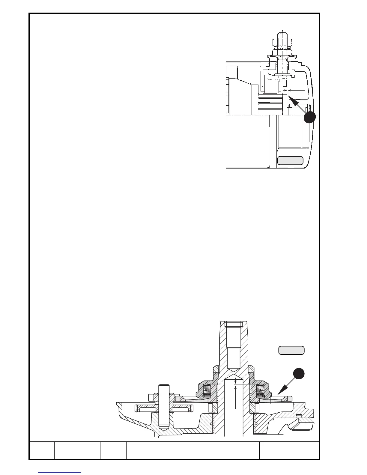
Check the axial clearance of the sprag clutch housing. It should be dimension P in
Chapter 15). At no or too little axial clearance the sprag clutch may not disengage
and the electric starter will be damaged.
Remove hex. nut R M34x 1,5 with socket
wrench 46 a/f, part no. 877 450, from crank-
shaft.
◆ NOTE: Hex. nut R with left hand
thread!
Maß
dim.
Pic. 201
6
6
Pic. 202
00235
00234

 Loading...


