Reference Modification no.
- 0 -
Page
180
Date
1997 02 01
Main
914 F
01478
2
3
1
4
Pic. 144
00089
I
U
Fit two each ignition cables g for the lower spark plugs into the glassfibre/
silicone protection hose T and route them between cylinder heads. Screw
spark plug connector h onto the ignition cables, secure with cable straps A
and plug them to the spark plugs according to the wiring diagram, see Pic.
139.
Fasten ignition cables for cylinder 1 - 3 and 2 - 4 with new cable strap on
coolant hose, see Pic. 139.
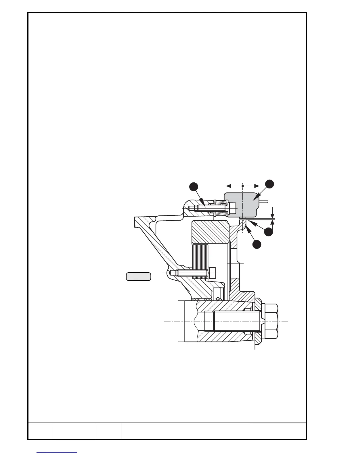
13.4.16)Exchange of external trigger coils
See Pic. 144 and 145.
Because of the shielding Y the trigger coil set T can be exchanged only in
pairs. Remove the fixation screws U with the distance sleeves I and clamps
and re-fit new trigger coil set. The stator O need not be removed in this case.
The trigger coil Q is adjustable only to a limited extent. The gap W between
pick-up and trigger cam E is dimension U. The axial position of the triggers
should be in the middle over the trigger cam and may be offset by max.
dimension I.
■ ATTENTION: Fit the clamps as to ensure perfect ground connection
between shielding and ignition housing.
dimensions new wear limit
See Chapter 15.

 Loading...


