Reference
Modification no.
- 0 -
Page
55
Date
1997 02 01
Main
914 F
01476
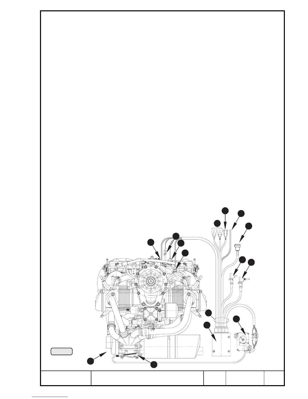
The electronic TCU (Turbo Control Unit) R is the central processing unit as
junction of all engine inputs. For functioning of the TCU following sensors and
pick-ups are required.
➪ airbox pressure sensor T
provides the actual boost pressure in the airbox
➪ static pressure sensor Y
conveys the prevailing atmospheric pressure
➪ throttle position potentiometer U
supplies actual position of carburetor throttle
◆ NOTE: From the inputs of the sensors T - U the target pressure is
determined.
➪ position of the waste gate
supplied directly from position of servo motor
➪ rev pick-up I
transmits the actual engine speed by the 5
th
trigger coil on ignition housing
➪ airbox-temperature sensor O
conveys the prevailing air temperature in the airbox
All the sensors are connected with the TCU via a common cable harness P.
Beside the power supply { for the TCU the following further connections are
provided on the cable harness.
➪ plug connections } for one each warning and caution lamp
➪ plug connection q for the 3-way solenoid valve
➪ 2 wires for an additional eletronic rev-counter w
➪ PC interface e for reading the TCU data by a computer.
Pic. 29
1
5
6
10
3
4
2
14
11
15
7
12
9
8
13
00139
Q turbo charger
W waste gate
E servo motor

 Loading...


