RTC
®
5 PC Interface Board
Rev. 1.9 e
7 Basic Functions for Scan Head and Laser Control
100
cally be temporarily extended by a corresponding
amount (see "Automatic Delay Adjustments",
page 107).
7.2.2 Scanner Delays
There
are three different types of scanner delays:
jump delay, mark delay and polygon delay. After
each vector or arc command, the RTC
®
5 inserts one
of these delays before the next command is started.
The command set_scanner_delays (see page 475)
defines the scanner delays. The time resolution for
the scanner delays is 10 µs.
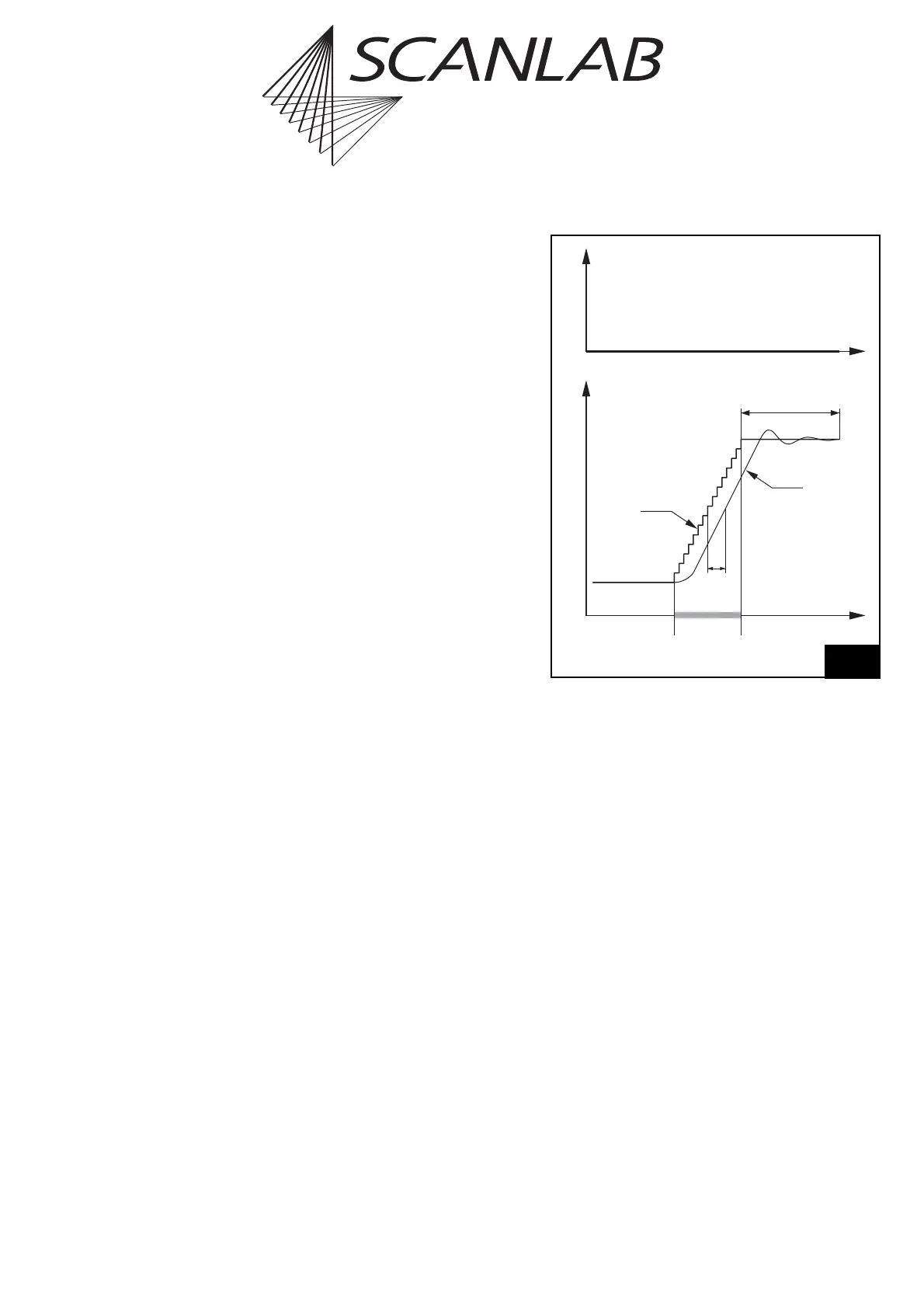
Jump Delay
When executing a jump command, the mirrors first
have to be accelerated up to the defined jump speed.
Because of the inertia of the mirrors, a lag occurs
between the set position and the real position –
see figure 30.
At the end of the jump, a certain settling time is
necessary for the mirrors to reach the set position
within some accuracy. To allow for the settling time
and for the lag, the RTC
®
5 inserts a jump delay after
each jump command (but not after goto_xy or
goto_xyz), before the next command is executed.
Note that the necessary settling time depends on the
selected jump speed. A higher jump speed usually
requires a longer jump delay. The jump delay value
can be defined by the user via the list command
set_scanner_delays.
The total time needed for the entire jump command
is the sum of the actual jump time and the jump
delay. It can be minimized by optimizing the jump
speed and the jump delay.
Time
Real
Position
Tracking
Error
Jump
Delay
Jump
Command
Set Position
(Microvectors)
LaserPosition
Scan head control timing during a jump command with a jump
delay. The laser is not turned on.