RTC
®
5 PC Interface Board
Rev. 1.9 e
4 Layout and Interfaces
47
Analog Output Ports
The RTC
®
5 provides two general purpose 12-bit
analog output ports, ANALOG OUT1 and
ANALOG OUT2
(1)
.
For programming the outputs see "12-Bit Analog
Output Ports", page 204.
The output voltage range of both analog output
ports is set to 0 V … 10 V.
Both signals are referenced to PC ground (GND). The
maximum current load of both signals is 5 mA.
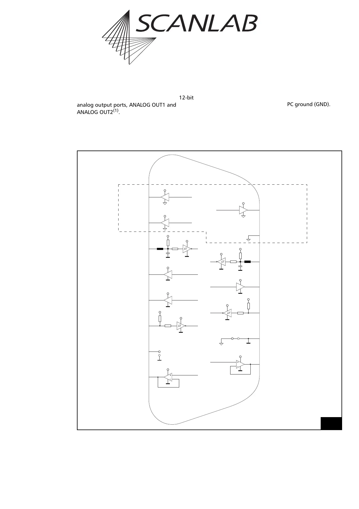
I/O Circuits
Figure 11 shows the I/O circuits of the 15-pin D-SUB
connector for the laser.
(1) The ANALOG OUT2 signal is also available
via the MARKING ON THE FLY connector (see page 51).
SN74LVC1G126
5V
74HC14
4k7
3.3V
3.3V
SN74LVC3G34
5V
74HC14
4k7
3.3V
3.3V
TLE2142
+12V
SN74LVC1G126
SN74LVC1G126
SN74LVC3G34
5V
5V
5V
74HC14
4k7
3.3V
3.3V
74HC14
4k7
3.3V
3.3V
+5V
TLE2142
+12V
SN74LVC3G34
5V
(9) LASER2
(11) /STOP
(12) DIGITAL OUT1
(13) DIGITAL IN1
(14) GND
(15) ANALOG OUT2
(10) GND2
(1)LASER1
(2)LASERON
(3)/START
(4)BUSY OUT
(5)DIGITAL OUT2
(6)DIGITAL IN2
(7)+5V
(8)ANALOG OUT1
(isolated for
opto-isolated
RTC
®
5 version)
(closed for
non opto-isolated
RTC
®
5 version)
I/O circuits of the 15-pin female D-SUB connector for the laser (LASER)