RTC
®
5 PC Interface Board
Rev. 1.9 e
7 Basic Functions for Scan Head and Laser Control
119
7.3.2 Image Field Size and Calibra-
tion
The size of the usable image field is determined by
the maximum scan angle and the focal length of the
objective or the working distance (i.e. the distance
between the input laser beam axis and the image
field).
The X and Y vector coordinates of a vector must be
specified as signed 20-bit numbers (i.e. as numbers
between – 524288 and +524287)
(1)
, however the
Z coordinates in a 3D system as signed 16-bit
numbers (i.e. as numbers between – 32768 and
+32767).
The ratio of a point coordinate in bits
(2)
and the
actual position of the point in millimeters is defined
by the calibration factor K.
Let a
0
denote the side length of the image field given
by the maximum scan angle. The theoretical cali-
bration factor is then K
0
=2
20
/a
0
[bits per mm
(2)
].
SCANLAB provides a rounded value for the cali-
bration factor K. This value is slightly larger than, but
close to, the theoretical value. The actual calibration
factor K can be read out from the used correction
table via the commands get_table_para (page 285)
or get_head_para (page 265).
Given the calibration factor K, the side length a of the
usable image field can be calculated:
a =2
20
/ K
Notes
The calibration factor is the same for the X and Y
direction. For 3D scan systems: K
z
= K
xy
/ 16.
Typical Image Field
In general, the size of the usable (or “typical”) image
field – dependent on the objective and the optical
configuration of the scan system – is smaller than the
maximum adjustable image field.
The scan head has a usable image field. If the laser
focus moves outside this field, some vignetting of the
laser beam can occur. The interior of the scan head
can be damaged due to excessive absorption of laser
power. Refer to your scan head operating manual’s
section on objectives.
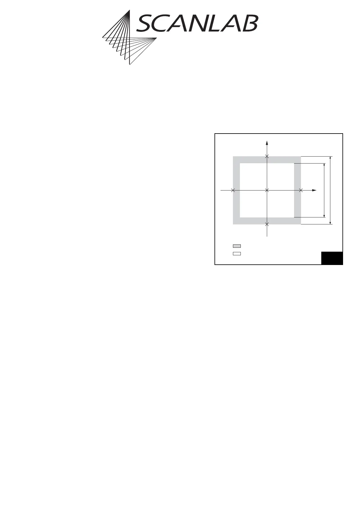
Compare the calculated side length a of the
maximum adjustable image field with the side
length b of the usable image field given in the
technical specifications of your scan head manual
(see figure 45).
If the laser focus shall be restricted to points
within the usable image field, the absolute values
of the X and Y coordinates (in bits) must be
smaller than the maximum value M, where M
is the calibration factor K multiplied by half the
side length of the usable image field:
M = K · b/2
(1) Actually, X and Y coordinates can be specified as signed 24-bit
numbers (i.e. as numbers between –8388608 and +8388607).
However, the complete value range [–8388608 … 8388607] is
only usable as a virtual image field e.g. for (enabled)
Processing-on-the-fly applications. The current coordinates will
be clipped to the value range [–524288 … 524287] (real image
field size) during runtime directly prior to use of the correction
table (also see page 120 and page 126).
(2) The expression “bits” is here synonymous with “digital control
value” (see footnote on page 93).
(0 | 0)(524.288 | 0)
(0
| 524.288)
(0
| +524.287)
(+524.287
| 0)
a
b
maximum adjustable image field
usable ("typical") image field
X
Y
Size of the usable image field