RTC
®
5 PC Interface Board
Rev. 1.9 e
7 Basic Functions for Scan Head and Laser Control
120
RTC
®
4 Compatibility Mode
With the RTC
®
5 (in RTC
®
5 mode), the image field
coordinates for the X and Y axes (but not the Z axis)
and all related parameters (e.g. jump speed or
wobbel amplitude) are specified as 20-bit values; in
RTC
®
4 compatibility mode they are specified as 16-
bit values (just like with the RTC
®
4).
In RTC
®
4 compatibility mode, the RTC
®
5 multiplies
the specified values by 16 (the permissible range of
values is correspondingly reduced). Also see section
"Increased Parameter Resolution" on page 33.
7.3.3 Virtual Image Field
X and Y coordinates can be specified as signed 24-bit
numbers (i.e. as numbers between –8388608 and
+8388607) for all vector and arc commands as well
as timed vector and arc commands (but not goto_xy
and goto_xyz). The current coordinates will be
clipped to the value range of the real image field
[–524288 … 524287] during runtime – after a coor-
dinate transformation (if applicable), after
Processing-on-the-fly corrections (if applicable), and
directly prior to use of the correction table (also see
page 126).
A virtual 24-bit image field is therefore available for
Processing-on-the-fly applications. Vector and arc
commands can also be loaded for objects up to 16
times larger than the real image field (in the
Processing-on-the-fly direction). For details see
page 187.
In addition, the extended value range of the virtual
image field can be used for utilizing the complete real
20-bit image field even if a coordinate transfor-
mation (as rotation, shrinkage or shift, see page 161)
is activated. If necessary, appropriate coordinate
values within the virtual image field can be defined,
which are subsequently transformed to coordinate
values within the real image field via the set coor-
dinate transformations (with the RTC
®
5’s prede-
cessor boards, if such coordinate transformations are
set, some edge points of the real image field are inac-
cessible).
7.3.4 Image Field Correction and
Correction Tables
Field Distortion
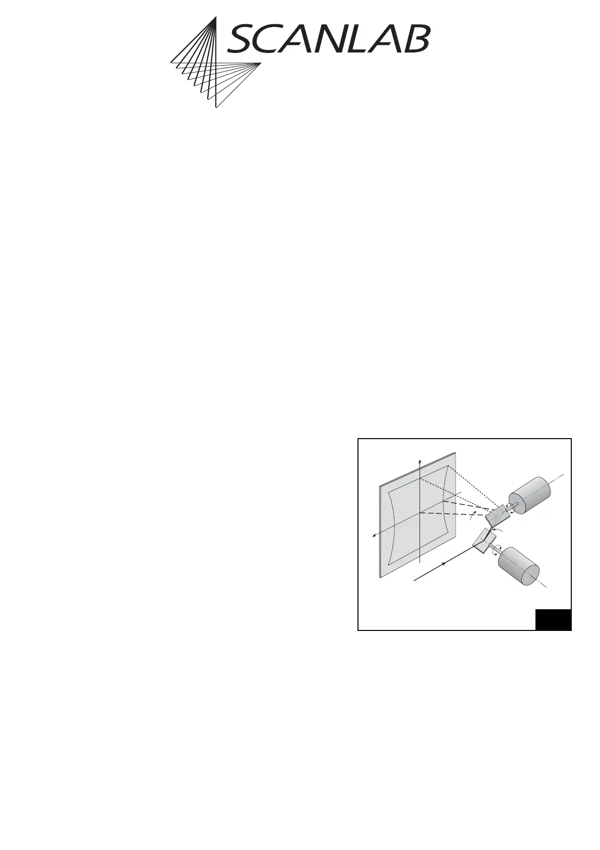
The deflection of a laser beam with a two-mirror
system results in three effects:
(1) The arrangement of the mirrors leads to a certain
distortion of the image field – see figure 46.
This distortion arises from the fact that
the distance between mirror 1 and the image
field depends on the size of the scan angles of
mirror 1 and mirror 2. A larger scan angle leads to
a longer distance.
(2) The distance in the image field is not proportional
to the scan angle itself, but to the tangent of the
scan angle. Therefore, the marking speed of the
laser focus in the image field is not proportional
to the angular velocity of the corresponding
scanner.
(3) If an ordinary lens is used for focusing the laser
beam, the focus lies on a sphere. In a flat image
field, a varying spot size results.
F
2
F
1
Galvanometer
Scanner 1
Beam in
Galvanometer
Scanner 2
Mirror 1
Mirror 2
Image Field
X
Y
Field distortion in a two-mirror deflection system