RTC
®
5 PC Interface Board
Rev. 1.9 e
7 Basic Functions for Scan Head and Laser Control
103
• For RTC5OUT.out version up to 525, zero-length timed
mark or arc commands behave like non-timed mark or
arc commands with a length of zero.
• For RTC5OUT.out versions up to 526, the behavior of
mark or arc commands with a length of zero is
independent of the laser control signals.
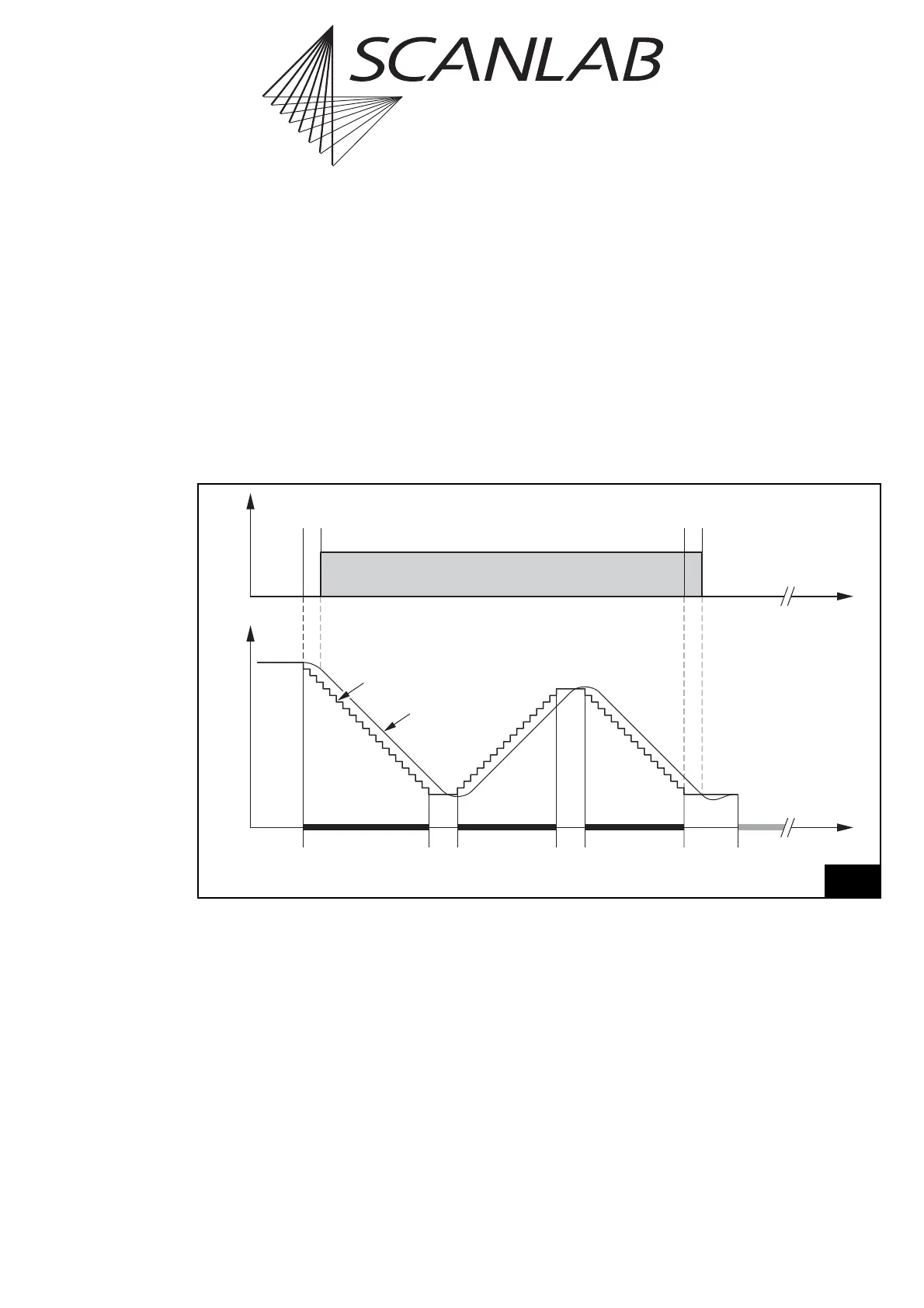
Polygon Delay
Between two successive mark or arc commands,
there is no need for a complete stop of the scanners.
Therefore the mark delay between two successive
mark or arc commands is replaced by a polygon delay
– see figure 33. Here, the laser remains on unless a
correspondingly smaller
edgelevel
was set via
set_delay_mode or set_delay_mode_list (see
page 104).
The mark delay and the polygon delay can be set
independently. In addition, the RTC
®
5 is able to vary
the length of the polygon delay, depending on the
angle between two marking vectors or the tangents
of the arcs. For details, see the section "Variable
Polygon Delay" on page 104.
Time
Laser
LaserOn
Delay
LaserOff
Delay
Polygon
Delay
Mark
Command
Mark
Command
Last Mark
Command
In This Polyline
Mark
Delay
Polygon
Delay
Jump
Command
etc.
Position
Set Position
Real Position
33
Scan head and laser control timing during a polyline with a constant polygon delay