RTC
®
5 PC Interface Board
Rev. 1.9 e
4 Layout and Interfaces
42
chapter 2.3 "Optional Functionality", page 27). After
activation, this connector outputs – depending on
the assigned correction tables (see above) – the same
signal types as the primary scan head connector.
Slot cover (Optional)
SCANLAB recommends using an additional slot cover
for connecting a second scan head or a Z axis. A
suitable slot cover with a 9-pin D-SUB connector –
with the same pin-out as the primary scan head
connector (see figure 4, page 41) – is available from
SCANLAB.
4.3.2 XY2-100 Converter (Optional)
SCANLAB’s optional XY2-100 converter converts the
RTC
®
5’s SL2-100 control signals (20 bit) into
XY2-100-compliant signals (16 bit), and converts the
scan system’s XY2-100 status signals into SL2-100-
compliant signals (see page 127).
The XY2-100 converter introduces a 10 µs runtime
latency to scan-system control. This runtime latency
can be compensated by increasing the LaserOn Delay
and LaserOff Delay by 10 µs each (see
set_laser_delays, page 442).
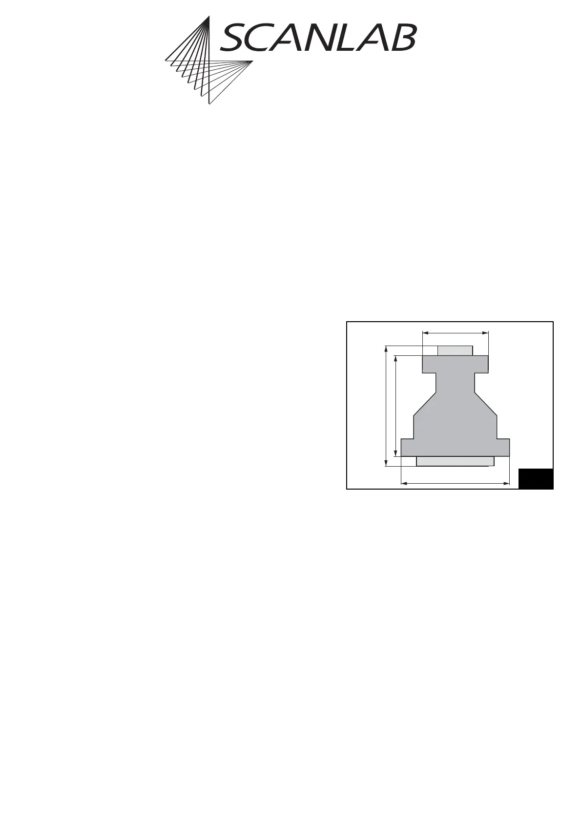
Figure 6 shows the dimensions of the XY2-100
converter.
The XY2-100 converter’s 9-pin D-SUB connector
should be directly plugged into the RTC
®
5’s primary
scan head connector or (via a short-as-possible 1:1
cable) connected to the corresponding pins of the
RTC
®
5’s secondary scan head connector (for the pin-
out, see figure 4 and figure 5 on page 41).
The XY2-100 converter’s 25-pin D-SUB connector is
compatible with scan heads that provide an XY2-100
standard interface. The pin-out is shown in figure 7,
page 43.
56.5
34.5
52
62
Thickness
12.5
25-pin female D-Sub
9-pin male D-Sub
Dimensions of the XY2-100 converter