RTC
®
5 PC Interface Board
Rev. 1.9 e
7 Basic Functions for Scan Head and Laser Control
131
7.4.3 CO
2
Mode
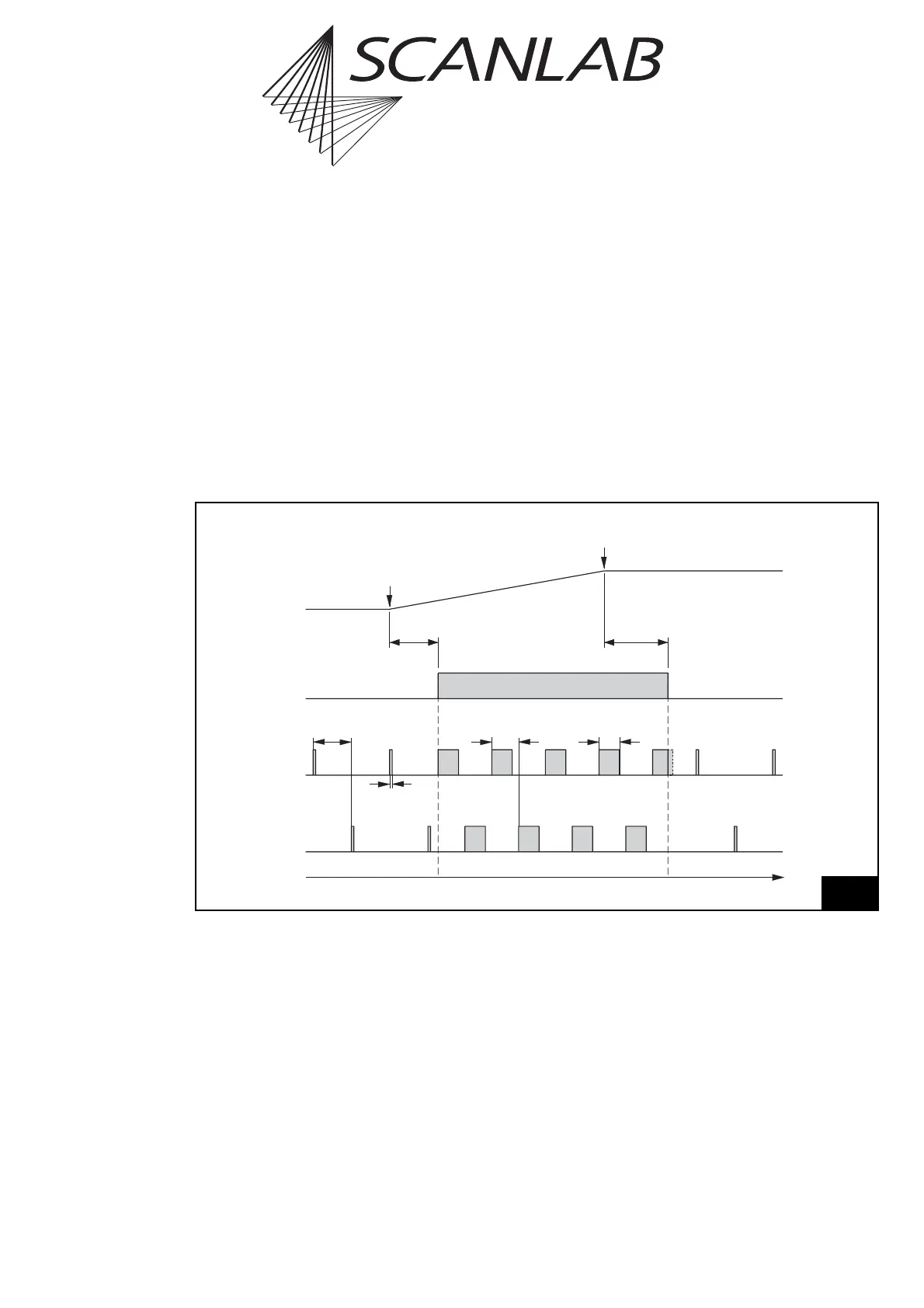
The command
set_laser_mode(0)
selects the CO
2
laser mode (laser mode 0). The laser control timing
diagram figure 48 shows the corresponding signals.
For “laser active” operation (if applicable after a
LaserOn delay and if enabled via set_laser_control or
enable_laser)
• The LASERON signal is switched on and
• Two alternating modulation signals are provided
at the LASER1 and LASER2 outputs with pulse
lengths and periods that can be defined via
set_laser_pulses, set_laser_pulses_ctrl or
set_laser_timing.
For “laser standby” operation (if applicable after a
LaserOff delay)
• The LASERON signal is switched off and
• Alternating standby pulses are provided at the
LASER1 and LASER2 outputs with pulse lengths
and periods that can be defined via set_standby
or set_standby_list.
Time
LaserOff
Delay
LaserOn
Delay
LASERON
"Laser active""Laser standby" "Laser standby"
Vector
Output
Start of
Vector
End of
Vector
½ Standby
Period
Standby
Pulse Width
LASER1
LASER2
½ Output
Period
Pulse Width
48
CO
2
mode
Laser control timing diagram for CO
2
mode (with active-high laser control signals)