RTC
®
5 PC Interface Board
Rev. 1.9 e
9 Programming Peripheral Interfaces
209
9.3 Control via External Signals
The previously-discussed input and output of
peripheral signals can be synchronized with scan
system and laser control, as described below:
• The necessary list commands can be inserted at
appropriate places in command lists.
• Execution of necessary control commands can be
made dependent on the current status of list
execution. For this, the list status can be
requested via read_status (see page 72) and the
list execution status via get_status (see page 73).
In addition, the BUSY list execution status is
provided via the BUSY OUT signal at the LASER
connector (page 46), at the EXTENSION 1
connector (page 49) and at the
MARKING ON THE FLY connector (page 51).
Moreover, the RTC
®
5 provides commands and inter-
faces (described in the following sections) that allow
external control signals (e.g. from a light-barrier or
from an encoder) to directly control and synchronize
execution of command lists or individual commands
(including the output of peripheral signals).
9.3.1 Starting and Stopping Lists via
External Control Signals and
Master/Slave Synchronization
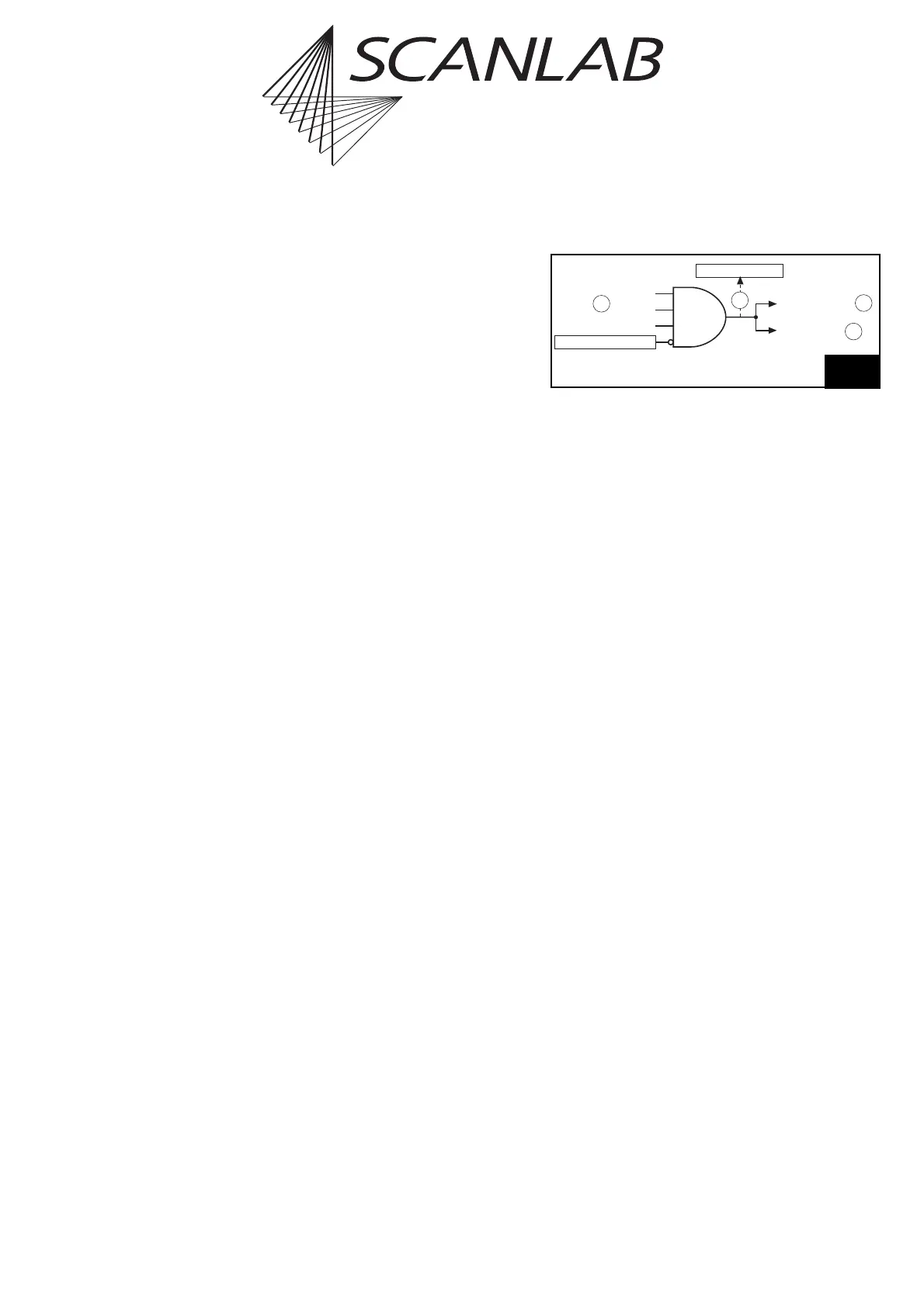
External List Stop
Via a signal at the inputs /STOP, /STOP2 or /Slave STOP,
or via the command simulate_ext_stop, an external
list stop can be initiated (see (1) and (3) in figure 57).
Like a call of the command stop_execution, this will
cause execution of the currently running list to be
immediately aborted and the “laser active” laser
control signals to be switched off (but not deacti-
vated).
Additionally, the 16-bit digital output port of the
EXTENSION 1 connector, the 8-bit digital output port
(DATA0 to DATA7) of the EXTENSION 2 connector as
well as the 2-bit digital output port and the two
12-bit analog output ports (ANALOG OUT1 and
ANALOG OUT2) of the LASER connector will be set to
the previously defined stop-case values – via
set_port_default – if these were not defined as “–1”.
The inputs for external stop signals (1) are always
unlocked so that an external stop can occur at any
time.
The /STOP input is accessible via the 15-pin D-SUB
LASER connector (see page 46), the /STOP2 input at
the MARKING ON THE FLY connector (see page 51).
Both signal inputs are internally connected to +3.3 V
via pull-up resistors (4.7 k). Both inputs are TTL
active-LOW and level sensitive. A list abort will be trig-
gered as soon as at least one of the two inputs is set
to LOW (i.e. to 0 V or ground) for at least 10 µs.
If the RTC
®
5 board is coupled via the MASTER or
SLAVE connector to another board, then external list
stops will be passed on from the master to the slave:
a Stop signal issued via the master board’s MASTER
output (4) is received at the slave board’s SLAVE input
(1), triggers a list stop at the slave board and is again
issued via the MASTER output (4) of the slave board.
List stops triggered by stop_execution are not
passed on from master to slave, but external list stops
triggered by simulate_ext_stop are passed on (also
see chapter 6.6.3 "Master/Slave Operation", page 84).
The command get_startstop_info queries the
current stop status (i.e. whether one of the inputs is
currently set to LOW) (2) and whether or not an
external list stop has occurred.
As of Version DLL 528, OUT 530, after setting
set_control_mode bit#1 = 1, the external start
queue’s entries get explicitly cancelled upon an
external list stop. For older versions and if
set_control_mode bit #1 = 0, the queue only gets
disabled.
/STOP
/STOP2
/Slave-STOP
ext-stop status
simulate ext-stop
1
/Master-STOP
/ext list stop
4
3
2
AND
External list stop (see text for description)