RTC
®
5 PC Interface Board
Rev. 1.9 e
7 Basic Functions for Scan Head and Laser Control
96
7.1.2 Microsteps
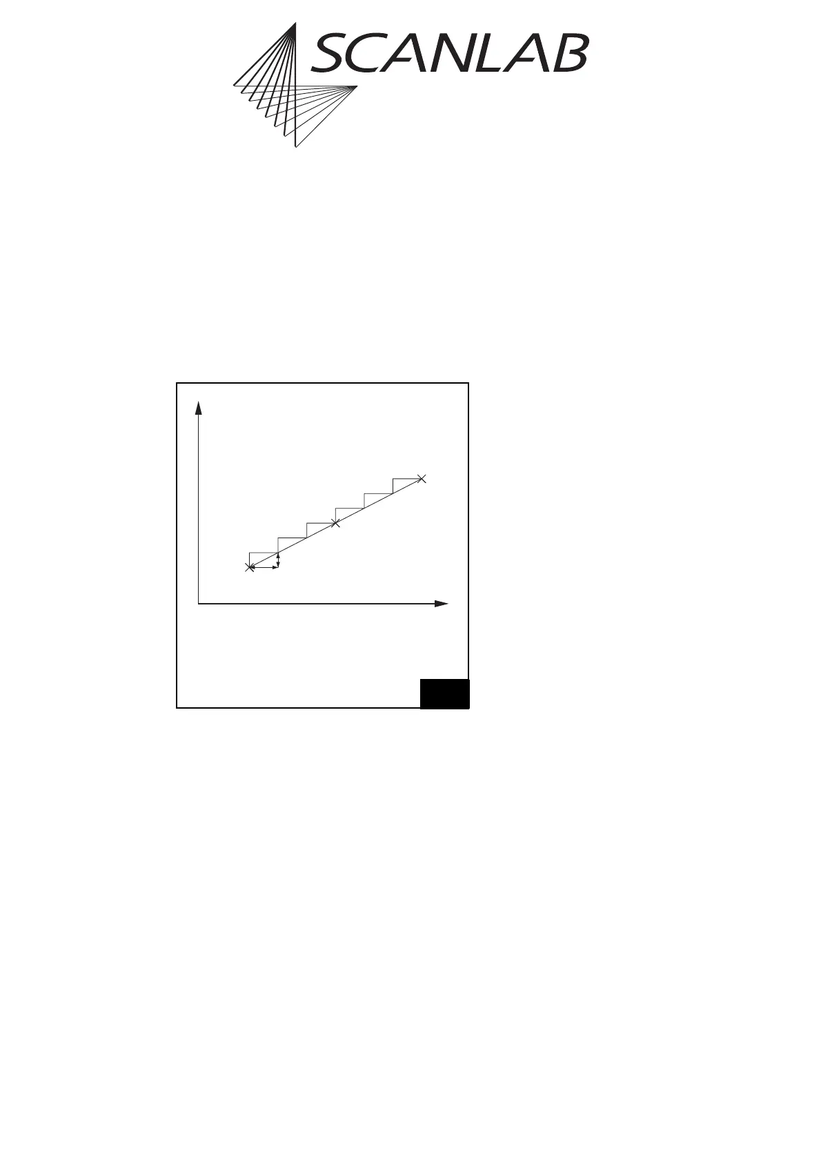
Each vector defined by a jump, mark or arc command
is divided into a number of small steps by the RTC
®
5.
These microsteps are transferred to the scan head at
a constant time rate (output period t). In controlling
its galvanometer scanners, the scan head implements
the steps via an analog servo loop.
Figure 29 shows how the X component of a vector is
divided into microsteps. The Y component is split up
in the same way.
The length s of each microstep is
s=v · t,
where v is the current jump speed (marking speed).
The output period t of the position update is usually
fixed at 10 µs. It is the same for 2D and for 3D appli-
cations. The output period cannot be set by the user.
Marking Time
The marking time consumed by any particular
marking process can be measured by calling the
command save_and_restart_timer (see page 397)
before and after the marking process. This command
saves the current value of the RTC
®
5’s integrated
timer and resets the timer value to 0. The measured
time can be read via the command get_time (see
page 286), which returns the timer value saved
during the most recent call of
save_and_restart_timer.
Notes
• You can implement direct execution of vectors
(without microvectorization) with the help of
microvector commands (see page 197).
•iDRIVE
®
scan systems let you execute jump and
goto_xy commands in either the (preconfigured
and microvectorized) vector mode or (after
enabling and activation) in jump mode (see
page 156).
•To compare RTC
®
5-internal
save_and_restart_timer time measurements to
external time measurements via the BUSY pin,
you should insert a list_nop between
save_and_restart_timer and set_end_of_list.
This ensures that any scanner delay will complete
before set_end_of_list. Without list_nop,
save_and_restart_timer includes the scanner
delay in its measurement even though it
completes only after set_end_of_list (and
therefore the BUSY pin is already low).
7.1.3 Marking Points
To mark a point outside of a polyline, you must switch
on the laser (i.e. the “laser active” laser control
signals) for the desired time period after a jump or
mark command (see laser_on_list,
laser_on_pulses_list, para_laser_on_pulses_list
and chapter 7.4 "Laser Control", page 128).
Outside or at the start of a polyline, you can also mark
a point (as of RTC5OUT.out version 527) by following
a jump command with a mark (or arc) command of
zero length (see page 102).
Within a polyline (as of RTC5OUT.out version 526),
points can also be marked by incorporating into the
polyline a timed vector or arc command with a zero
vector or arc length (see page 198).
t
x
Dt
Dx
(t
0
| x
0
)
(t
1
| x
1
)
(t
0
+i·Dt | x
0
+i·Dx)
29
x
0
X coordinate of the current output
position before scanning the vector
x
1
X coordinate of the end position
of the vector
t step period (10 µs)
The X component of a vector is split up into microsteps.