RTC
®
5 PC Interface Board
Rev. 1.9 e
6 Developing User Applications
70
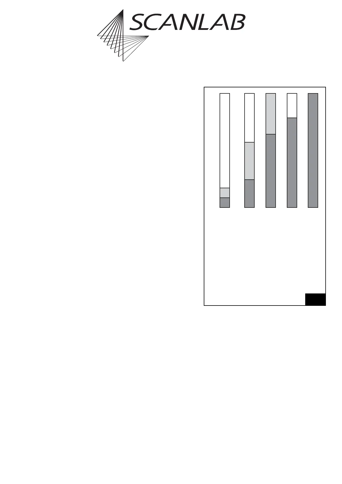
6.3.2 Configuring the List Memory
For compatibility, SCANLAB preconfigures the
RTC
®
5’s list buffer area such that “List 1” and “List 2”
can each accept 4,000 list commands. The protected
“List 3” then owns the remaining 1040576 of the 2
20
storage positions (see Configuration (a) in figure 27).
Users can also reconfigure the buffer area via the
command config_list (see page 243). For example, if
an application only needs one list, then the RTC
®
5’s
entire memory can be treated as a single list with a
total capacity of 2
20
positions (see Configuration (e)
in figure 27). In this case, the single list (“List 1”) can
be loaded with up t o 2
20
commands. The buffer areas
will generally be configured so that “List 1” will
occupy the lower positions, “List 2” the intermediate
positions, and “List 3” the uppermost positions.
When configuring the buffer areas, note that “List 1”
must contain at least one storage position and that
the total sum of storage positions for “List 1” and
“List 2” must not exceed 2
20
. Other than that, the
sizes of “List 1” and “List 2” can be configured as
desired (e.g. 0 positions for “List 2”, see Configu-
ration (d) or (e) in figure 27). During configuration,
the protected “List 3” buffer area automatically
receives remaining memory not assigned to “List 1”
or “List 2”.
The configuration process does not alter the contents
of the buffer memory. Repeating the call with
differing parameters is therefore nondestructive.
When subsequently altering the configuration, you
should observe the following:
• List boundaries should not be moved to within an
eventual subroutine.
• If a “List 3” region is assigned to the list area
(“List 1” or “List 2”), the region’s protection will
be removed.
• Valid jump addresses specified in jump
commands might become invalid if the configu-
ration is altered (see "Jumps", page 81).
• If the protected buffer area (“List 3”) is made
larger, defragmentation might be needed to
make the newly assigned memory area usable
(see "Index Management and Defragmentation"
on page 79).
1 “List 1” (list buffer)
2 “List 2” (list buffer)
3 “List 3” (protected buffer area)
(a) Standard configuration (left: boundary
memory positions of the three buffer areas):
config_list(4000, 4000)
(b)
config_list(Mem1, Mem2)
with
Mem1
> 0,
Mem2
2
20
-
Mem1
(c)
config_list(Mem1, –1)
with
Mem1
> 0
(d)
config_list(Mem1, 0)
with
Mem1
> 0
(e)
config_list(-1, x)
with
x
as desired
27
2
20
-1
3999
7999
0
1
1
3
1
2
1
2
3
1
2
3
(a) (b) (c) (d) (e)
4000
8000
Examples of valid list buffer configurations